Photoelectric conversion machine with function of tightly plugging optical fiber connectors

An optical fiber connector and converter technology, which is used in optical fiber transmission, coupling of optical waveguides, light guides, etc., can solve problems such as falling off and loose fiber connectors, and achieve the effect of preventing loosening or adjusting the tightness, reliable connection, and stable movement.

Inactive Publication Date: 2018-07-06
河南趣读信息科技有限公司
View PDF1 Cites 1 Cited by
  • Summary
  • Abstract
  • Description
  • Claims
  • Application Information

AI Technical Summary

Problems solved by technology

[0005] The present invention overcomes the deficiencies of the prior art, provides a photoelectric converter that can pull the optical fiber connector toward the direction close to the optical fiber interface, and ensures that the optical fiber connection is firm, and solves the problem that the optical fiber connector is easy to loosen or fall off from the photoelectric converter

Method used


Image

  • Photoelectric conversion machine with function of tightly plugging optical fiber connectors
  • Photoelectric conversion machine with function of tightly plugging optical fiber connectors
  • Photoelectric conversion machine with function of tightly plugging optical fiber connectors

Examples


Embodiment 1

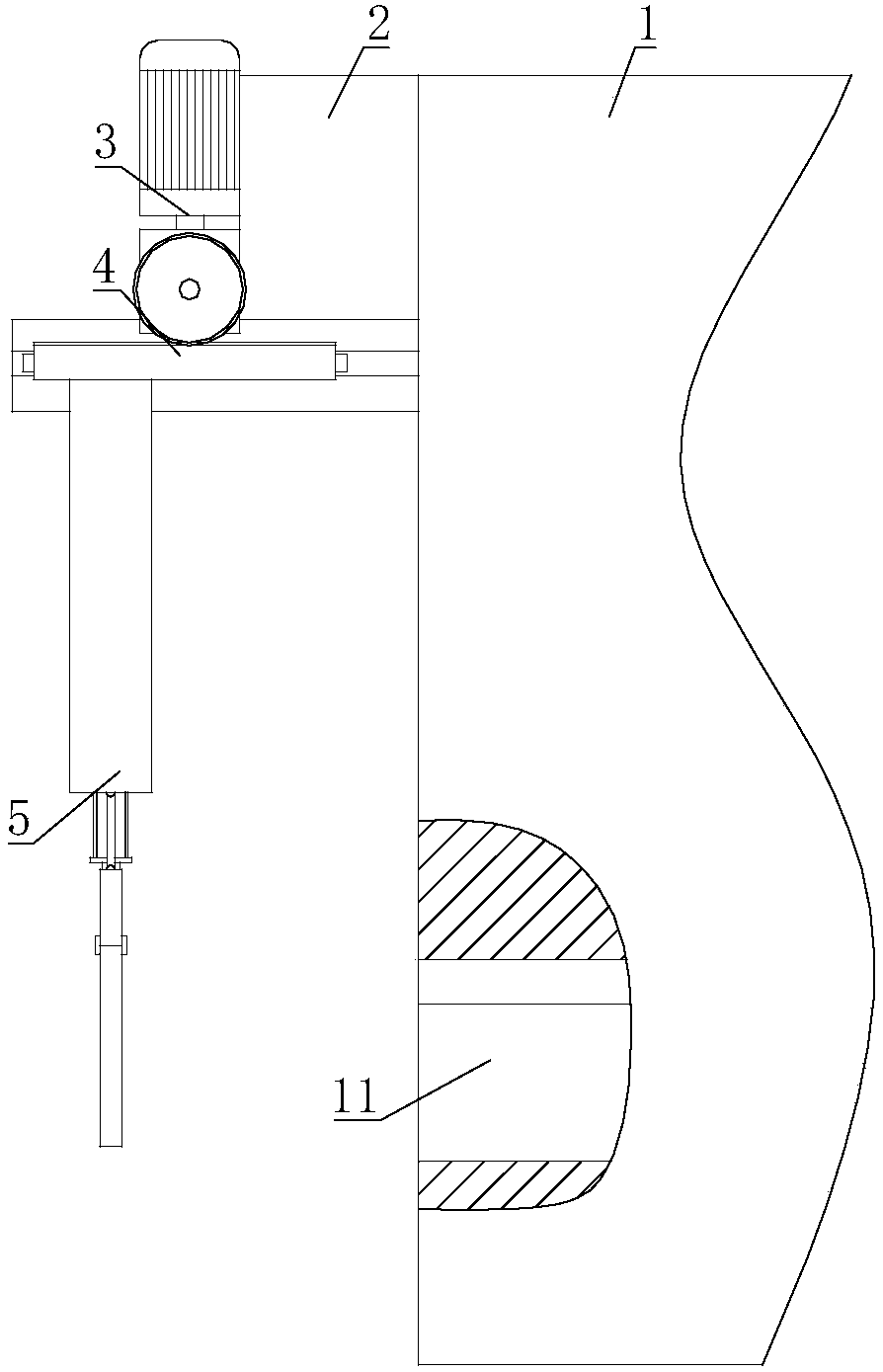
[0024] A photoelectric converter capable of inserting optical fiber connectors tightly, including a main body 1 of the converter, on which an optical fiber interface 11 is arranged; the main body 1 of the converter is connected with a mounting plate 2, and a driving mechanism 3 is installed on the mounting plate 2 , the output end of the driving mechanism 3 is connected to the rack and pinion mechanism 4, and the other end of the rack and pinion mechanism 4 is connected to the clamping mechanism 5 for clamping the optical fiber connector.

[0025] The driving mechanism 3 of the present invention can drive the rack and pinion mechanism 4 to move, and the rack and pinion mechanism 4 drives the clamping mechanism 5 to move. Therefore, the optical fiber connector clamped by the clamping mechanism 5 can move towards the direction close to the optical fiber slot, and the optical fiber connector can be inserted into the optical fiber interface more firmly, avoiding the situation that ...

Embodiment 2

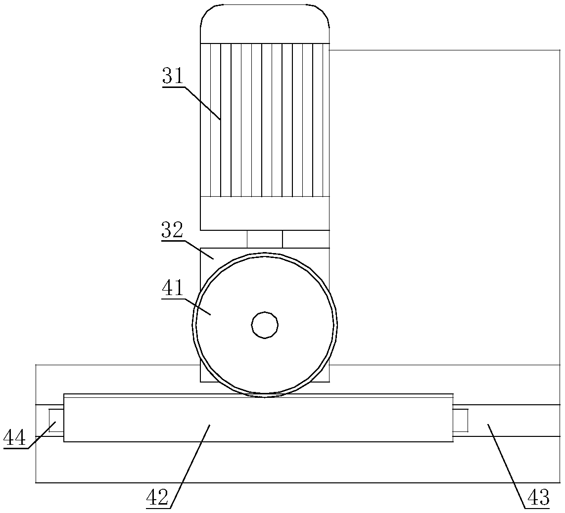
[0027] On the basis of Embodiment 1, the drive mechanism 3 includes a motor 31, the output shaft of the motor 31 is connected with a speed reducer 32, the motor 31 and the speed reducer 32 are all installed on the mounting plate 2, the output shaft of the speed reducer 32 and the gear The gear of the rack mechanism 4 is connected.

[0028] When the motor 31 is started, the motor 31 drives the reducer 32 to act, and the reducer 32 drives the rack and pinion mechanism 4 to operate, so that the clamping mechanism 5 and the optical fiber connector can move accurately under the drive of the rack and pinion to ensure smooth plugging, or It is used to adjust the tightness of the optical fiber connector inserted into the optical fiber interface 11.

Embodiment 3

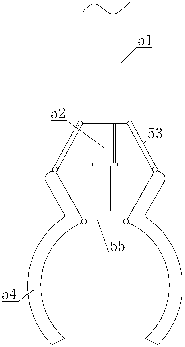
[0030] On the basis of Embodiment 1 or Embodiment 2, the rack and pinion mechanism 4 includes a gear 41, the gear 41 is connected to the output shaft of the drive mechanism 3, the gear 41 is engaged with a rack 42, and the clamping mechanism 5 is fixed on the rack 42 ; the mounting plate 2 is also connected with a chute 43 , the rack 42 is fixed with a slide bar 44 , and the slide bar 44 is sleeved in the chute 43 .

[0031] When the driving mechanism 3 drives the gear 41 to rotate, the rack 42 moves horizontally under the drive of the gear 41, so that the rack 42 can drive the clamping mechanism 5 and the optical fiber joint to move, thereby achieving the purpose of preventing loosening of the optical fiber joint or adjusting the tightness. During the moving process of the rack 42, the slide bar 44 always slides in the chute 43, so that the rack 42 moves more smoothly, and also ensures that the optical fiber connector does not shake greatly during the moving process, reducing ...


PUM


Abstract

The invention relates to the field of photoelectric conversion machines, in particular to a photoelectric conversion machine with a function of tightly plugging optical fiber connectors. The technicalscheme includes that the photoelectric conversion machine with the function of tightly plugging the optical fiber connectors comprises a conversion machine body; an optical fiber interface is arranged on the conversion machine body; a mounting plate is connected onto the conversion machine body, a driving mechanism is mounted on the mounting plate, a gear and rack mechanism is connected with an output end of the driving mechanism, and a clamping mechanism for clamping the optical fiber connectors is connected with the other end of the gear and rack mechanism. The photoelectric conversion machine has the advantages that the optical fiber connectors can be pulled towards the directions close to the optical fiber interface, accordingly, optical fibers can be assuredly firmly connected with the optical fiber interface, and the problem that existing optical fiber connectors are easy to loosen or fall out from existing photoelectric conversion machines can be solved.

Description

technical field [0001] The invention relates to the field of photoelectric conversion machines, in particular to a photoelectric conversion machine capable of tightly inserting optical fiber joints. Background technique [0002] At present, the photoelectric conversion machine generally includes a laser diode, a first light transmission part coupled with the first light transmission part, a second light transmission part and a photodiode, and after the laser diode emits an optical signal, the light signal enters the first light transmission part, The optical signal transmitted through the second optical transmission part and finally enters the photodiode is converted into an electrical signal through the photodiode, so as to achieve the purpose of photoelectric conversion. With the continuous advancement of science and technology, the network has become an indispensable part of people's life. The photoelectric conversion machine is a device similar to a baseband digital mod...

Claims


Application Information

Patent Timeline
Patent Type & Authority Applications(China)
IPC IPC(8): G02B6/42H04B10/25
CPCG02B6/4201H04B10/25
Inventor 李云鹏
Owner 河南趣读信息科技有限公司
Why Eureka
Try Eureka