Large-area plane efficient cleaning device

A cleaning device and a large-area technology, applied in the field of cleaning, can solve the problems of high difficulty in manual cleaning, scratching the glass surface, and high investment cost, and achieve the effect of cleaning effect, energy saving, environmental protection, easy disassembly and transportation, and saving cleaning time.

Pending Publication Date: 2018-07-10
天津创来智能光伏科技有限公司
View PDF10 Cites 6 Cited by
  • Summary
  • Abstract
  • Description
  • Claims
  • Application Information

AI Technical Summary

Problems solved by technology

Some small photovoltaic power stations use manual cleaning methods, generally using mops, rubber scrapers or soft rags for cleaning. The disadvantage of this method is that scratches will inevitably occur on the glass panel during the cleaning process, and the glass surface will be scratched. Two people are required to work together, and the efficiency is relatively low; large and medium-sized photovoltaic power stations are difficult to clean manually, and generally use mechanical cleaning methods, high-pressure water gun cleaning: water is pressurized to form a water-vapor mixture, and the dust on the surface of the photovoltaic panel is washed away, clean The effect is good, so it is widely used by many photovoltaic power stations, but the disadvantage is that it has a large demand for water and electricity, and a large amount of sewage will be formed during the cleaning process, which will pollute the environment; cleaning by cleaning vehicles: large water consumption, almost no damage to the panel, and high efficiency , but it needs to be used in a wide and flat area, and the input cost is high; in addition, there is mechanical dust removal technology, which uses mechanized brushes combined with water spray to rinse the automatic dust removal device of the photovoltaic panel, etc., and the dust is swept away by mechanical force, but some machines are clean The effect is poor, the cost is high, and it will also pollute the environment

Method used


Image

  • Large-area plane efficient cleaning device
  • Large-area plane efficient cleaning device
  • Large-area plane efficient cleaning device

Examples


Embodiment Construction

[0057] In order to enable those skilled in the art to better understand the solution of the present invention, the present invention will be further described in detail below in conjunction with the accompanying drawings and specific embodiments. Apparently, the described embodiments are only some of the embodiments of the present invention, not all of them. Based on the embodiments of the present invention, all other embodiments obtained by persons of ordinary skill in the art without making creative efforts belong to the protection scope of the present invention. It should be noted that representation and description of components and processes that are not related to the present invention and known to those of ordinary skill in the art are omitted from the drawings and descriptions for the purpose of clarity.

[0058] In describing the present invention, it should be understood that the terms "upper", "lower", "front", "rear", "left", "right", "top", "bottom", "inner", " T...


PUM


Abstract

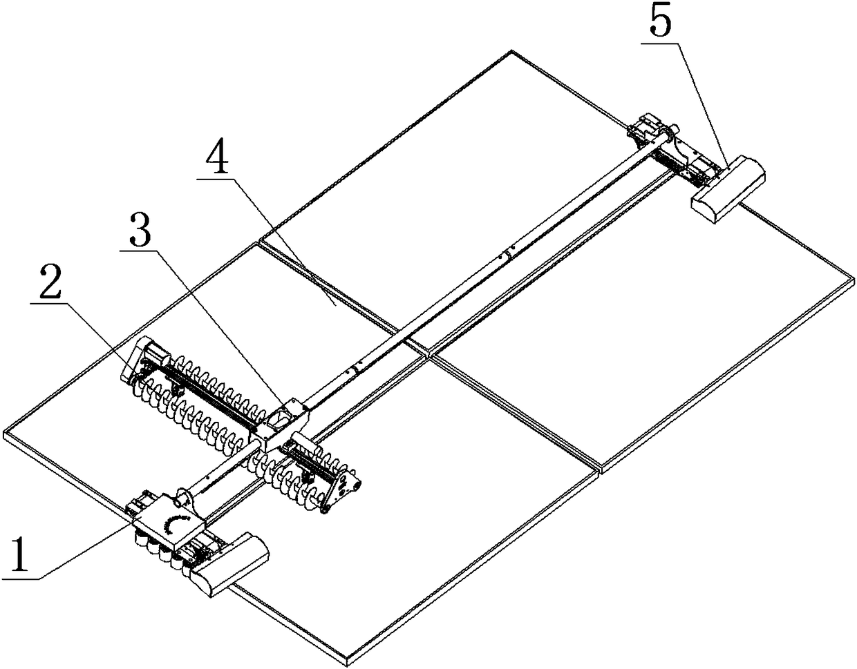
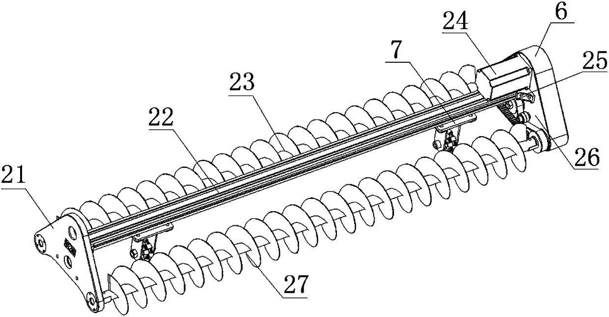
The invention provides a large-area plane efficient cleaning device. The device comprises a first edge brush assembly, a second edge brush assembly, a double-roller brush cleaning assembly, a surfaceto be cleaned and a conduction assembly; and the first edge brush assembly and the second edge brush assembly are arranged at the two ends of the surface to be cleaned correspondingly, the conductionassembly is arranged between the first edge brush assembly and the second edge brush assembly, the conduction assembly is connected with the first edge brush assembly and the second edge brush assembly correspondingly, the double-roller brush cleaning assembly is arranged below the conduction assembly, and the double-roller brush cleaning assembly is connected with the conduction assembly. The device has the beneficial effects that the cleaning efficiency can be effectively improved, the cleaning time is saved, the device is suitable for large-area photovoltaic power stations of various different types, the investment cost is low, the device is convenient to detach and transport, and the device has the advantages of being time-saving and labor-saving, good in cleaning effect, energy-savingand environment-friendly and the like.

Description

technical field [0001] The invention belongs to the technical field of cleaning, and in particular relates to a large-area plane high-efficiency cleaning device. Background technique [0002] Solar energy is an inexhaustible renewable resource. Under the increasingly urgent form of tangible energy on the earth, solar energy, as a clean energy source, is getting more and more attention and promotion. Solar photovoltaic power generation has become a global concern and focus Developed new energy projects. In the practical application of solar photovoltaic power generation, photovoltaic panels are the most important unit of power generation, and their output power is directly affected by the intensity of sunlight. During the use of photovoltaic panels, because they are exposed to the outdoors day and night, dust and other impurities in the air will Falling on it will cause insufficient light, which will reduce the efficiency of photovoltaic power generation, and form hot spots,...

Claims


Application Information

Patent Timeline
Patent Type & Authority Applications(China)
IPC IPC(8): B08B1/04B08B1/00B08B13/00H02S40/10
CPCH02S40/10B08B1/002B08B1/008B08B1/04B08B13/00Y02E10/50
Inventor 许盛之
Owner 天津创来智能光伏科技有限公司
Why Eureka
Try Eureka