
Electroplating bath

A technology of electroplating tank and electroplating solution, which is applied in the direction of electrodes, electrolytic processes, electrolytic components, etc., can solve the problems of uneven cathode electroplating, uneven left and right electroplating, etc., and achieve the goal of improving uneven electroplating, uniform current distribution, and optimizing electroplating parameters Effect

Active Publication Date: 2018-07-10
UNIV OF ELECTRONICS SCI & TECH OF CHINA +1
View PDF9 Cites 3 Cited by
  • Summary
  • Abstract
  • Description
  • Claims
  • Application Information

AI Technical Summary

Problems solved by technology

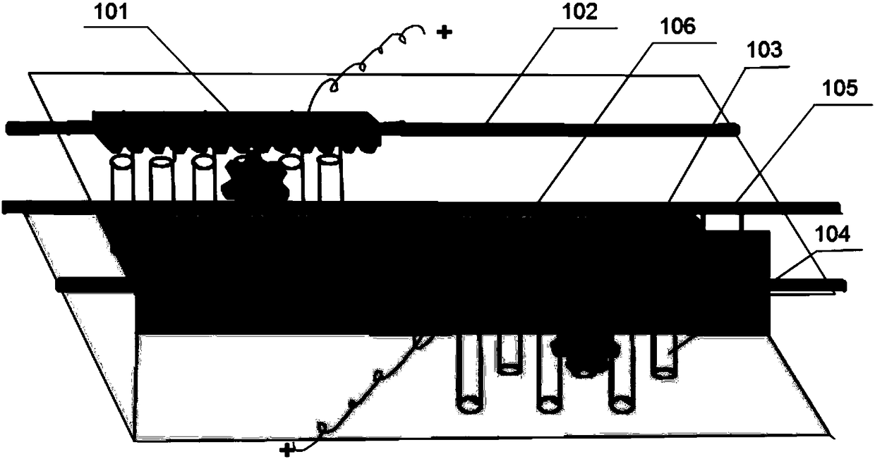
[0005] In view of the above, the purpose of the present invention is to solve the problems in the design of spin plating in the prior art that it is difficult to be compatible with the front and rear processes of the traditional plating line, the current problem caused by the relative movement of the anode, and the complexity of the existing spin plating design. The present invention provides an electroplating tank with an anode structure that swings back and forth. Compared with the traditional rotary electroplating, the electroplating tank has low cost, strong compatibility, and simple operation, and can improve the unevenness of the left and right plating while improving the unevenness of the upper and lower cathodes. question

Method used


Image

  • Electroplating bath
  • Electroplating bath
  • Electroplating bath

Examples


Embodiment 1

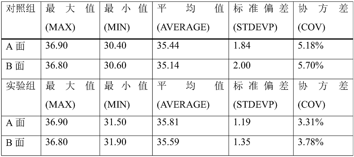
[0034] In this embodiment, the experimental group and the control group are designed to carry out comparative experiments. In the experimental group, the anodes on both sides swing back and forth to carry out circular motion. The anode is static, and the electroplating test is carried out under the same conditions as the experimental group. The experimental group and the control group are tested for uniformity after the electroplating is completed: use the CMI 700 copper thickness tester to test the surface copper thickness, and the electroplating uniformity adopts the method of uniformly taking points. The size of the electroplating plate is 160mm×110mm, and 150 points are evenly taken .

[0035] The experimental results are shown in Table 1:

[0036]

[0037] Table 1

[0038] The results show that the uniformity of copper thickness has been improved to a certain extent, the COV (Coefficient of Variance) value of side A has increased from 5.18% to 3.31%, the COV value of...

Embodiment 2

[0041] This example demonstrates the application potential of the new electroplating tank equipment in electroplating copper blind vias through electroplating blind via experiments.

[0042] The design of this embodiment is to use the anode reciprocating swing mode to carry out cyclical movement. Add brightener, inhibitor and leveling agent to the bath of the electroplating tank in sequence. figure 1 The new type of electroplating tank shown is used for electroplating filling blind hole experiments. The hole diameter of the electroplating cathode blind hole plate is 85 μm, and the hole depth is 140 μm.

[0043] After the electroplating is completed, use a metallographic microscope to observe the blind hole slices, such as figure 2 For the metallographic diagram of blind hole slices, by adjusting the electroplating additives, the novel electroplating tank provided by the invention can also realize blind hole filling. The experimental results show that the new electroplating d...


PUM

PropertyMeasurementUnit
pore sizeaaaaaaaaaa

Abstract

The invention provides an electroplating bath and belongs to the technical field of electroplating equipment. The electroplating bath comprises a bath body, transmission devices, a power supply device, anodes and a cathode. The cathode is fixed to the middle of the bath body. Fixed guide rails parallel to the cathode are correspondingly arranged on the two sides of the cathode. The transmission devices are arranged on the corresponding fixed guide rails. Each transmission device comprises a load-bearing sliding component and a traction component for pulling the load-bearing sliding component to move in the axial direction of the corresponding fixed guide rail in a reciprocating manner. Multiple long and short titanium baskets loaded with the anodes and distributed in a staggered manner arehung on the load-bearing sliding component, and the load-bearing sliding component is connected with the power supply device through wires. By the adoption of the electroplating bath, the uniform current distribution in all regions of a cathode plate is ensured, and the length, weight and the like are reduced greatly compared with a traditional gantry line steel plate, so that the operability ishigher, the maintenance is facilitated as well, the operation cost is lowered, the electroplating parameters can be optimized, and the electroplating bath has good flexibility and provides a new ideafor improving the actual production process.

Description

technical field [0001] The invention belongs to the technical field of electroplating equipment, and in particular relates to an electroplating tank with a reciprocating swing anode structure. Background technique [0002] With the rapid development of electronic product technology, printed circuit boards (Printed Circuit Board, PCB) are rapidly developing in the direction of high density, high integration, thin lines, small apertures, and thinning, and the requirements for circuit precision are also increasing. High, which puts forward higher and higher requirements for the uniformity of the thickness of the electroplated copper layer. [0003] At present, the electroplating process mainly includes the traditional static suspension electroplating and the subsequent development of the spin electroplating. The anode of the traditional static suspension electroplating is static, and the electroplating is realized by rack plating + cathode movement. However, for electroplating...

Claims


Application Information

Patent Timeline
Patent Type & Authority Applications(China)
IPC IPC(8): C25D17/10C25D5/04C25D21/10
CPCC25D5/04C25D17/10C25D21/10Y02P10/20
Inventor 倪修任王守绪陈苑明何为王翀周国云李清华艾克华王青云
Owner UNIV OF ELECTRONICS SCI & TECH OF CHINA
Learn More