Power supply structure, water tank and toilet
A water tank and toilet technology, which is applied to water supply devices, sanitary equipment for toilets, household appliances, etc., can solve the problems that the water tank cannot be placed in the battery box, increase the cost of the battery box, and easily cause water leakage accidents, so as to save the water in the water tank. The effect of space, space saving and failure reduction
- Summary
- Abstract
- Description
- Claims
- Application Information
AI Technical Summary
Problems solved by technology
Method used
Image

Examples
Embodiment 1
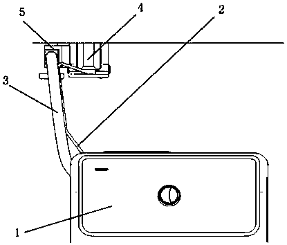
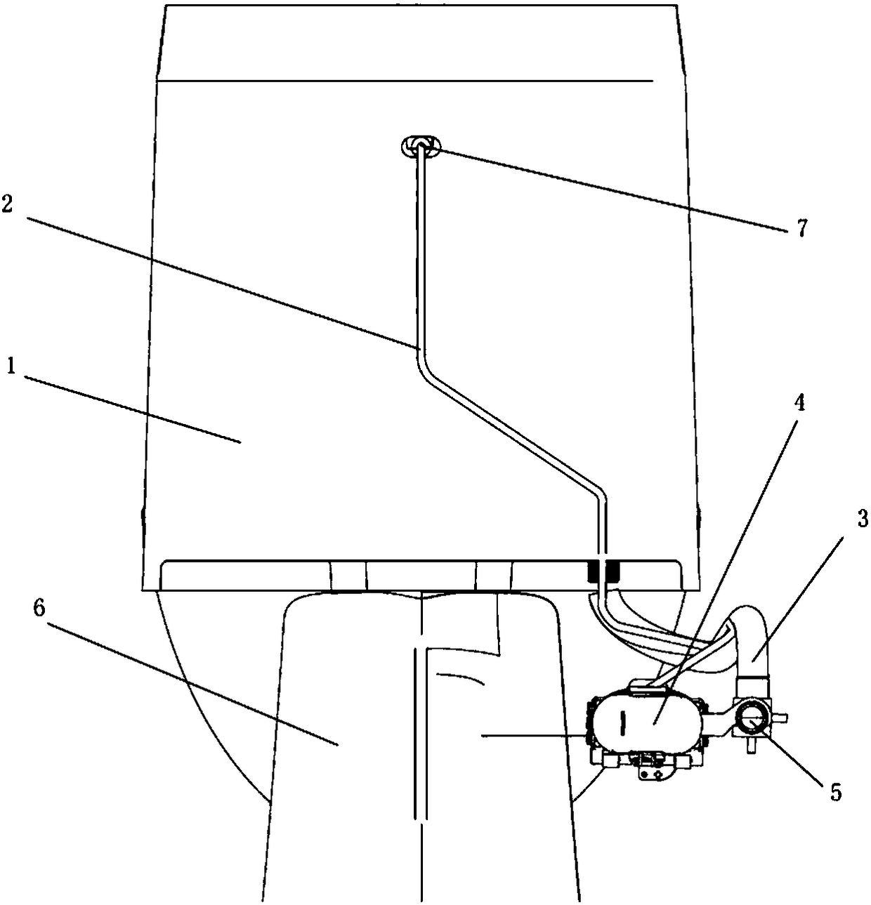
[0035] Such as Figure 1-3 As shown, the power supply structure of the present invention includes a water tank and a battery box, and the battery box is located outside the water tank; the battery box is connected to electrical devices through power lines and / or data lines. The water tank communicates with one end of the water inlet pipe; the power line and / or data line are arranged along the direction of the water inlet pipe; the other end of the water inlet pipe communicates with the angle valve; the battery box is fixedly connected to the angle valve. A hole is arranged on the back of the water tank; the power line and / or data line lead into the water tank through the hole. There are more than two power lines and / or data lines, which are respectively connected to more than two electrical devices; the electrical devices include disinfection devices and / or light emitting devices and / or human body sensors and / or heart rate sensors and / or Or a pressure sensor and / or a body fat...
Embodiment 2
[0039] In this embodiment, the power lines and / or data lines may also be in multiple groups, respectively connected to a plurality of battery boxes or electrical devices, so as to meet the requirement of installing multiple electronic devices on the toilet seat. Other parts that are the same as those in Embodiment 1 will not be repeated here.
Embodiment 3
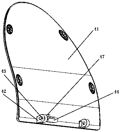
[0041] Such as Figure 4 As shown, the power line and / or data line can also be routed through the hinge between the toilet lid upper cover and the toilet seat, and the toilet lid upper cover and the toilet seat are connected by a hinge; hinge ears and rotating shafts are also included , the hinge ear is provided with a hole, and the hole on the hinge ear is matched with the rotating shaft; it also includes a power line and / or a data line, and the power line and / or data line are accommodated in the inner space of the hinge ear Inside, one end of the power cable and / or data cable is connected to the electrical device, and the other end of the power cable and / or data cable is drawn out; the cable is wound on the rotating shaft. This method can be used in common with the hole described in Embodiment 1, or it can be used alone. Other parts that are the same as those in Embodiment 1 will not be repeated here.
PUM
 Abstract
Description
Claims
Application Information
 - R&D
- Intellectual Property
- Life Sciences
- Materials
- Tech Scout
- Unparalleled Data Quality
- Higher Quality Content
- 60% Fewer Hallucinations
Browse by: Latest US Patents, China's latest patents, Technical Efficacy Thesaurus, Application Domain, Technology Topic, Popular Technical Reports.
© 2025 PatSnap. All rights reserved.Legal|Privacy policy|Modern Slavery Act Transparency Statement|Sitemap|About US| Contact US: help@patsnap.com