Novel adjustable damping device

A damping device and adjustable technology, which is applied in the design features of springs/shock absorbers, shock absorbers, mechanical equipment, etc., can solve the problems of human body or contact with things, affecting the service life of the product, and the impact of jumping frames. To achieve the effect of simplifying the structure, facilitating adjustment and reducing the quantity

Pending Publication Date: 2018-07-10
江苏杰豪电气有限公司
View PDF9 Cites 0 Cited by
  • Summary
  • Abstract
  • Description
  • Claims
  • Application Information

AI Technical Summary

Problems solved by technology

[0003] The traditional pop-up floor socket includes a panel, a jumper frame and a pop-up mechanism. The functional parts are arranged on the jumper frame. The torsion of the spring is realized. Since the torsion of the torsion spring directly acts on the jumping frame, and there is no damping device, the impact force of the jumping frame is very large when it bounces off, which will generate a lot of noise and affect the service life of the product. It may also cause harm to the human body or contact things, so a damping device is usually set to buffer the speed of the jumping frame, but this type of damping device is pre-installed in the damping seat because the damper and the spring are pre-loaded. The force is also fixed and non-adjustable when the damping device is assembled; due to the influence of measurement errors and other factors, there is often a deviation between the time when the frame jumps up and the ideal value in actual use

Method used


Image

  • Novel adjustable damping device
  • Novel adjustable damping device
  • Novel adjustable damping device

Examples


Embodiment Construction

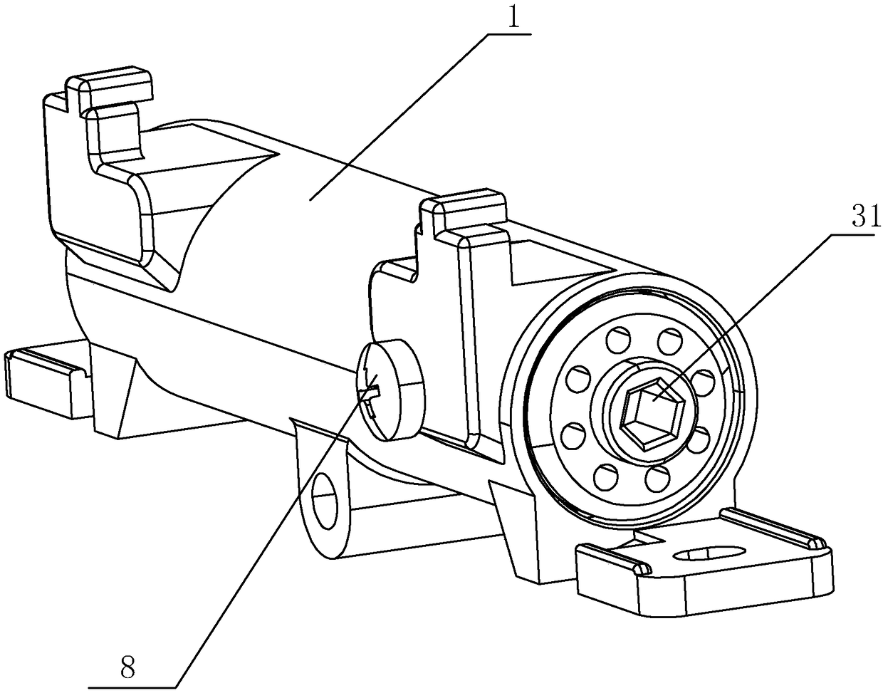
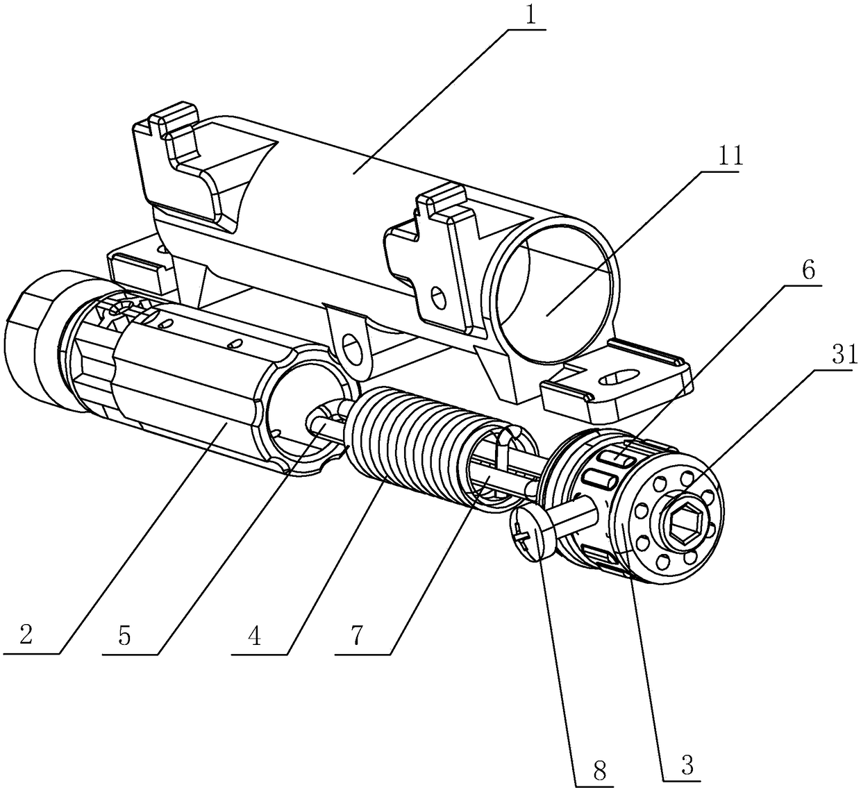
[0017] Refer to the attached Figure 1 to Figure 4 The embodiment of a novel adjustable damping device of the present invention will be further described in detail.

[0018] A novel adjustable damping device comprises a jump seat 1, a mounting hole 11 is arranged on the jump seat 1, a damping shaft 2 is arranged at one port of the mounting hole 11, and an adjusting shaft 3 is arranged at the other port, and the damping shaft A spring 4 is arranged between 2 and the adjusting shaft, and the mounting hole 11 is sealingly matched with the adjusting shaft 3 and the damping shaft 2 to form a cavity for filling damping oil, wherein the adjusting shaft 3 is sleeved with a sealing ring, and the adjusting shaft 3 The shaft 3 is sealed with the mounting hole 11 through a sealing ring, the damping shaft 2 is also sleeved with a sealing ring, and the damping shaft 2 is sealed with the mounting hole 11 through the sealing ring;

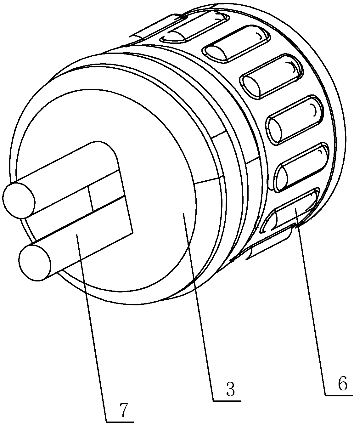
[0019] One end of the damping shaft 2 is inserted with the ...


PUM


Abstract

The invention discloses a novel adjustable damping device which comprises a bounce seat. A mounting hole is formed in the bounce seat. A damping shaft and an adjusting shaft are arranged on the mounting hole. A spring is arranged between the damping shaft and the adjusting shaft. The mounting hole is in sealed fit with the adjusting shaft and the damping shaft to form a cavity used for being filled with damping oil. A first clamp piece is connected to one end of the damping shaft in an inserted manner, and the other end of the damping shaft extends to the outer portion of the mounting hole. The adjusting shaft is fixedly sleeved with a friction ring, the adjusting shaft and the mounting hole are in clearance fit through the friction ring, a second clamp piece is connected to one end of theadjusting shaft in an inserted manner, and an adjusting portion is arranged at the other end of the adjusting shaft. One end of the spring is connected with the first clamp piece, and the other end of the spring is connected with the second clamp piece. In the process that the adjusting shaft drives the spring to rotate through the second clamp piece, fiction force is generated between the friction ring and the mounting hole and can offset rotating force generated by acting of the spring on the adjusting shaft, the magnitude of damping force is adjusted, the structure is simple, and adjustment is convenient.

Description

technical field [0001] The invention relates to a novel adjustable damping device. Background technique [0002] The ground plug is a socket installed on the ground or similar places and used to connect with fixed wiring. It is usually used as the terminal and outlet of the ground wiring system to take out the power, signal and data in the ground wiring system. It is mainly used in large-bay indoor places such as offices, airports, hotels, shopping malls, and families, and has a wide range of uses. [0003] The traditional pop-up ground socket includes a panel, a jump frame and a pop-up mechanism. The functional parts are arranged on the jump frame. The torsion force of the spring is realized, because the torsion force of the torsion spring acts directly on the jump frame, and there is no damping device, so that the impact force of the jump frame when it bounces is large, which will generate a lot of noise and affect the service life of the product. It may also cause harm ...

Claims


Application Information

Patent Timeline
IPC IPC(8): F16F7/04F16F11/00H01R13/46
CPCH01R13/46F16F7/023F16F7/04F16F2232/02F16F2222/12F16F2222/04F16F2224/025F16F2230/0005
Inventor 刘正政
Owner 江苏杰豪电气有限公司
Why Eureka
Try Eureka