Solar photovoltaic traffic ground indication luminous system and production process thereof

A technology of solar photovoltaic and lighting system, applied in the field of solar photovoltaic traffic ground indicating lighting system and its production technology, to achieve the effect of facilitating pedestrians and vehicles to use, eliminating poor indicating effect and improving bearing capacity

Inactive Publication Date: 2018-07-13
山东佑蓝新能源科技有限公司
View PDF0 Cites 2 Cited by
  • Summary
  • Abstract
  • Description
  • Claims
  • Application Information

AI Technical Summary

Problems solved by technology

[0004] The purpose of the present invention is to provide a solar photovoltaic traffic ground indicator lighting system and its production process, so as to solve the aforementioned problems in the prior art

Method used


Image

  • Solar photovoltaic traffic ground indication luminous system and production process thereof
  • Solar photovoltaic traffic ground indication luminous system and production process thereof
  • Solar photovoltaic traffic ground indication luminous system and production process thereof

Examples


Embodiment 1

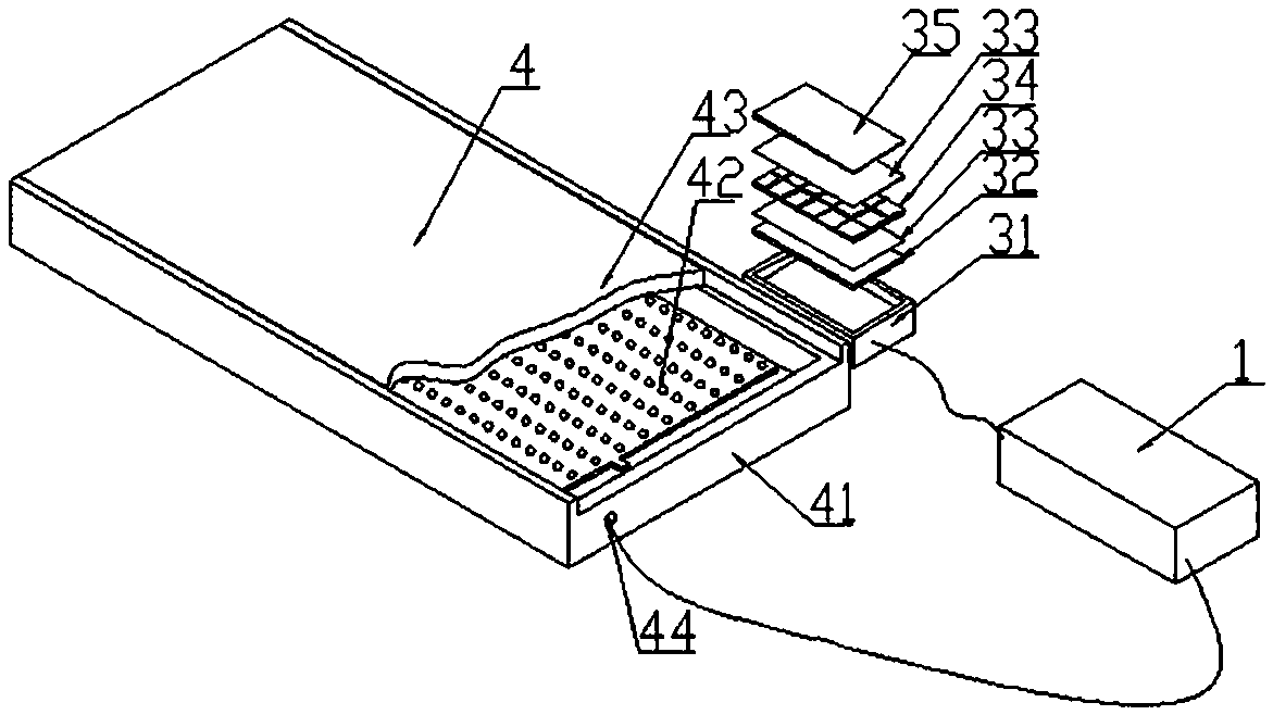
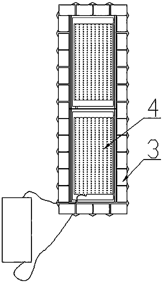
[0027] Embodiment 1: After the above components are produced at the factory end, such as figure 2 As shown, the light-emitting module 4 and the photovoltaic storage module 3 are connected together through the wire 2 and the power supply and control combination module 1, and the combination of the present invention is made into a strip-shaped zebra crossing structure, which is assembled by slotting on the road surface Processing, after embedding the light-emitting module 4, lay a circle of photovoltaic power storage modules 3 around it, and connect all the photovoltaic power storage modules 3 through wires, collect and store power in real time, and realize the assisting guidance of traffic lights at traffic intersections through the above structure.

Embodiment 2

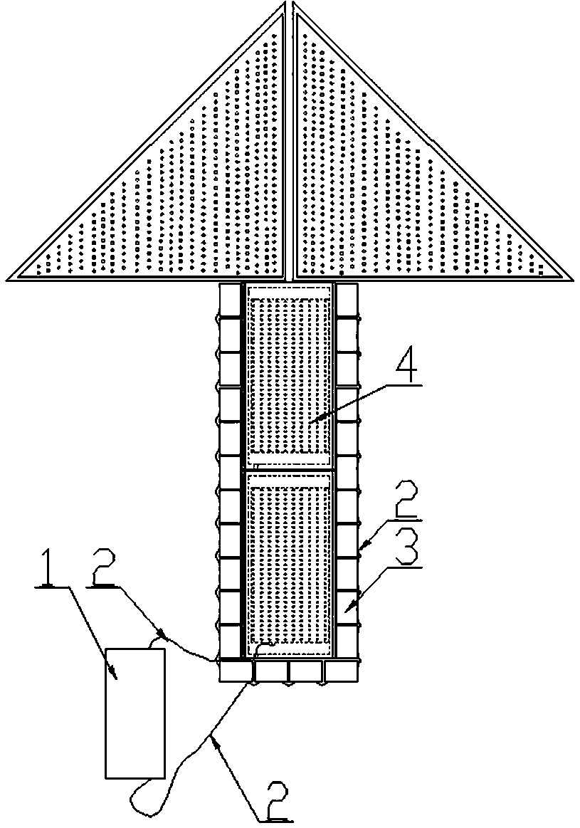
[0028] Embodiment 2: After the above components are produced at the factory end, such as image 3 As shown, the light-emitting module 4 and the photovoltaic storage module 3 are connected together through the wire 2 and the power supply and control combination module 1, and the combination of the present invention is made into an arrow-shaped guide line structure, which is assembled by slotting on the road floor Processing, after embedding the light-emitting module 4, lay a circle of photovoltaic power storage modules 3 around it, and connect all the photovoltaic power storage modules 3 through wires 2, collect and store power in real time, and realize the assistance and guidance of traffic lights at traffic intersections through the above structure .

[0029] The combination structure of the present invention is not limited to the above two general combination forms, and it can evolve into the assembly of various guiding line structures under the guidance of the above structu...


PUM


Abstract

The invention discloses a solar photovoltaic traffic ground indication luminous system. The solar photovoltaic traffic ground indication luminous system comprises a luminous module and photovoltaic power storage modules, wherein the luminous module and the photovoltaic power storage module are both connected into a whole by wires and a power supply and control combination module; the luminous module comprises a bearing frame; a plurality of luminophers are horizontally putted inside the bearing frame; a euphotic cover plate is arranged at the top of the bearing frame; the photovoltaic power storage modules are arranged around the luminous module in a surrounding manner; an electric plate bearing framework is arranged at the bottoms of the photovoltaic power storage modules; a polyvinyl fluoride composite film, a first EVA (Ethylene Vinyl Acetate) adhesive film, a solar battery series plate, a second EVA adhesive film and an antiskid protecting plate are sequentially arranged in the electric plate bearing framework from the bottom end. According to the solar photovoltaic traffic ground indication luminous system disclosed by the invention, due to the adoption of the design, a luminous device and a photovoltaic acquisition and electric storage device are both paved on the ground, solar energy is effectively utilized, traffic lights are extended to the ground and can be favorablyused by pedestrian and vehicles, and further the defects that existing traffic indication lights are poor in indication effect and are affected by weather are eliminated.

Description

technical field [0001] The invention relates to the technical field of solar ground indication, in particular to a solar photovoltaic traffic ground indication lighting system and a production process thereof. Background technique [0002] In the current traffic indication field, pedestrian and vehicle walking instructions are mostly realized through road indicator lights fixed on the top of the road. This kind of road indication device has disadvantages, which are mainly reflected in: 1. It must be realized by an external power supply, which has the following advantages: The limitations of installation and energy supply; 2. Its indication effect is weak, and there is a disadvantage that the front car blocks the sight of the rear car; 3. In rainy and foggy days, the visibility is low, and at some large intersections, the efficiency of traffic indication is affected. [0003] Aiming at the disadvantages of the existing technology, as a technical person in this industry, how...

Claims


Application Information

Patent Timeline
Patent Type & Authority Applications(China)
IPC IPC(8): E01C17/00H02S40/38H02S30/10H01L31/048
CPCE01C17/00H01L31/048H02S30/10H02S40/38Y02E10/50Y02E70/30
Inventor 李耀光孟春梅周新华
Owner 山东佑蓝新能源科技有限公司
Why Eureka
Try Eureka