Eureka AIR delivers breakthrough ideas for toughest innovation challenges, trusted by R&D personnel around the world.

A constant, fatigue stress test device and test method

A technology of fatigue stress and testing equipment, which is applied in the direction of measuring equipment, testing material strength by applying stable tension/pressure, testing material strength by applying repetitive force/pulsation force, etc. Well simulate the damage process of structural parts and other problems to achieve the effect of solving the problem of synergy

Active Publication Date: 2020-10-09
NO 59 RES INST OF CHINA ORDNANCE IND
View PDF18 Cites 0 Cited by
  • Summary
  • Abstract
  • Description
  • Claims
  • Application Information

AI Technical Summary

Problems solved by technology

Although this device can be used for long-term exposure tests in outdoor atmospheric environments, it cannot apply fatigue alternating stress, nor can it simulate the damage process of structural parts well.

Method used


Image

  • A constant, fatigue stress test device and test method
  • A constant, fatigue stress test device and test method
  • A constant, fatigue stress test device and test method

Examples


Embodiment 1

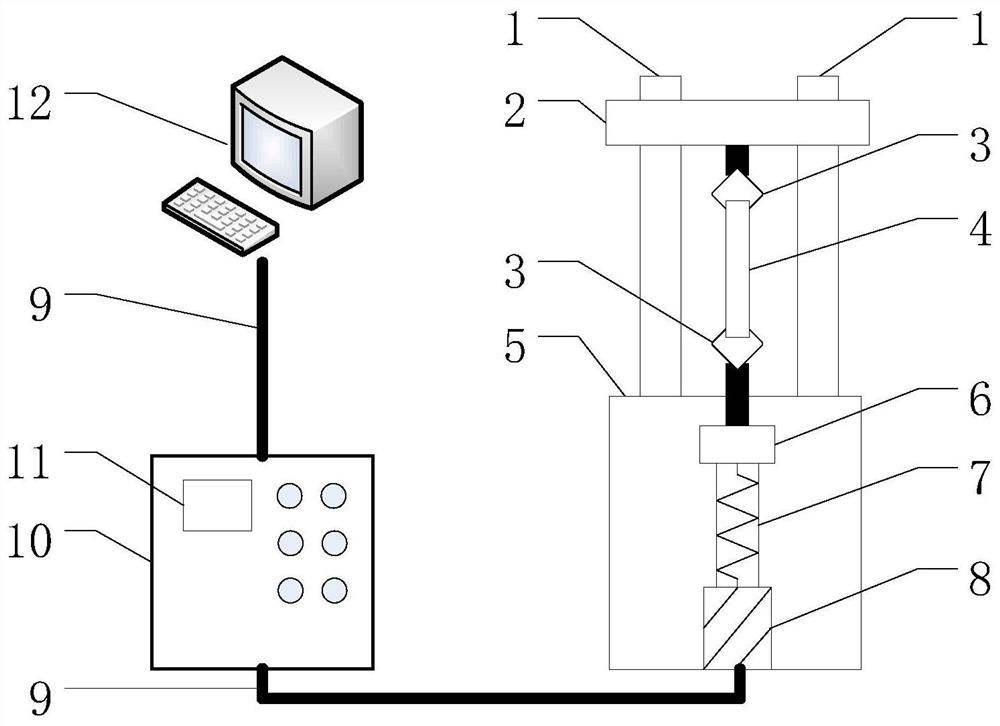
[0032] Constant, fatigue stress test apparatus such as figure 1 As shown, including a workbench, a transparent frame is set on the workbench surface 5, and a clamping part 6 for fixing the specimen is set on the frame. The clamping part 6 is connected to the axial stress loading system, and the axial stress loading system It includes a force sensor 6, a lead screw 7 and a servo motor 8 arranged in sequence in the workbench. The force sensor 6 is located between the clamping part 6 and the lead screw 7 to detect the loaded mechanical load. One end of the lead screw 7 is connected to the force The sensor 6 and the other end of the lead screw 7 are connected to the output end of the servo motor 8; the input end of the servo motor 8 is connected to a control system for controlling the operation of the servo motor 8.

[0033]The control system includes a control cabinet 10, and a digital controller 11 is arranged in the control cabinet 10, and the digital controller 11 is respectiv...

Embodiment 2

[0042] In order to facilitate further understanding of the environment-constant fatigue stress synergy test method of the present invention, the environment-stress synergy test is described in detail by taking a dumbbell-shaped tensile sample as an example.

[0043] The sample is a dumbbell-shaped tensile sample with a straight section of 20 mm × 1.5 mm, and the sample is vertically fixed between the upper and lower clamping parts.


PUM


Abstract

The invention provides a constant and fatigue stress testing device and a testing method. The testing device comprises a worktable, wherein a transparent framework is arranged on a tabletop of the worktable; the framework is provided with a clamping part for fixing a test piece; the clamping part is connected with an axial stress loading system; the axial stress loading system comprises a force sensor, a screw rod and a servo motor, which are arranged in the worktable in sequence; the force sensor is located between the clamping part and the screw rod; one end of the screw rod is connected with the force sensor and the other end of the screw rod is connected with an output end of the servo motor; the servo motor is connected with a control system. The testing method comprises the followingsteps: firstly, placing the testing device in a natural environment; then mounting the test piece on the clamping part of the testing device; applying constant stress and / or fatigue stress on the test piece, so as to realize a cooperative effect on the test piece by environment and dynamic loads. A damaging process on a structural part can be simulated and reappeared relatively well.

Description

technical field [0001] The invention relates to a device and method for damage assessment of structural parts, in particular to a constant fatigue stress test device and a test method for simulating the environmental damage process of structural parts under natural environmental conditions. Background technique [0002] Structural parts will be affected by various environmental factors during actual use, and are always in a certain corrosive environment, for example, damp and accompanied by SO 2 , Cl - Environmental factors such as corrosive media will have a significant impact on structural parts, causing structural corrosion damage. When the structural parts are in use or in operation, especially when the working stress is far less than the allowable stress, the structural parts are prone to sudden fracture damage or premature failure, especially for key stressed structural parts of aviation, military products and bridges , once a sudden fracture occurs, catastrophic acc...

Claims


Application Information

Patent Timeline
Patent Type & Authority Patents(China)
IPC IPC(8): G01N3/38G01N3/08
CPCG01N3/08G01N3/38G01N2203/0003G01N2203/0005G01N2203/0017G01N2203/005G01N2203/0073G01N2203/024G01N2203/0268
Inventor 苏艳钟勇舒畅杨万均朱玉琴封先河罗来正吴帅滕俊鹏
Owner NO 59 RES INST OF CHINA ORDNANCE IND
Why Eureka
Eureka Blog
Learn More