Projection lens
A projection lens and lens technology, applied in the field of projection lenses, can solve the problems of large distortion, poor imaging quality, and inability to redistribute projection beams, etc., and achieve the effect of large numerical aperture and high imaging quality
- Summary
- Abstract
- Description
- Claims
- Application Information
AI Technical Summary
Problems solved by technology
Method used
Image
Examples
Embodiment 1
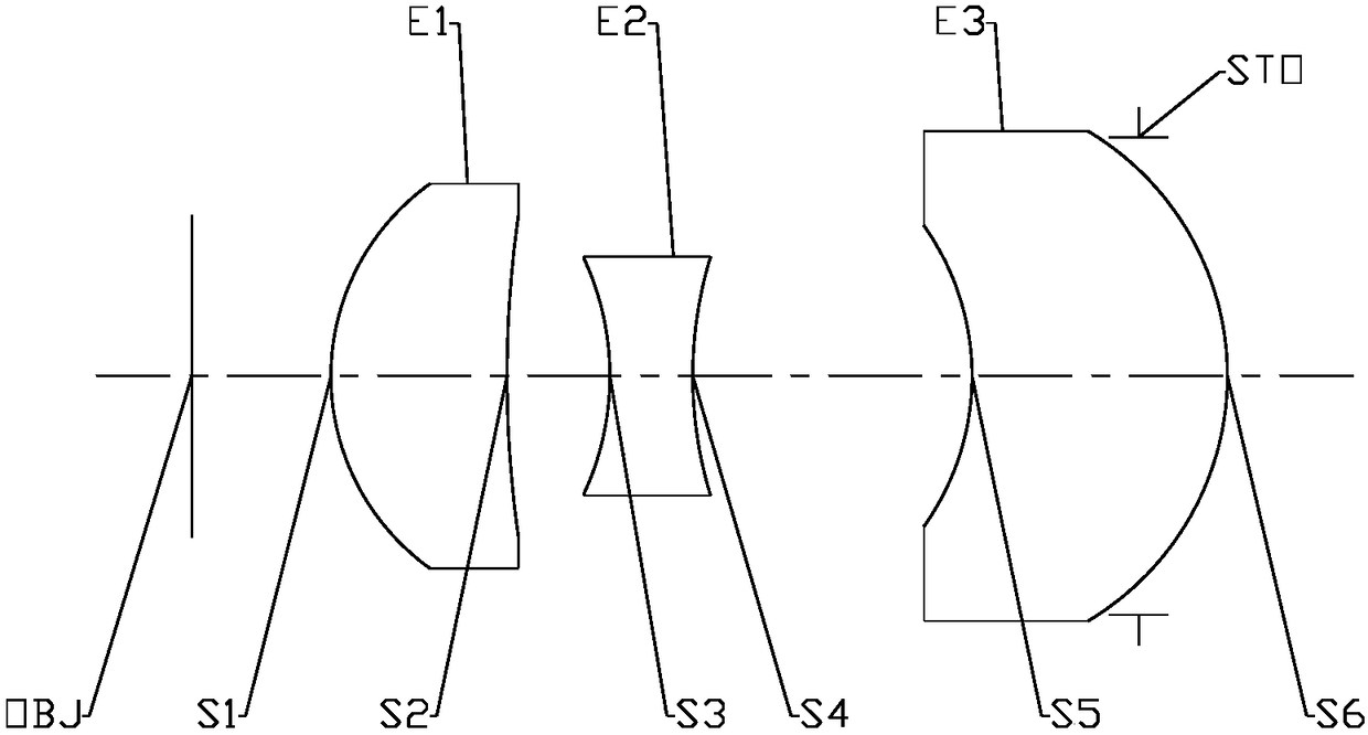
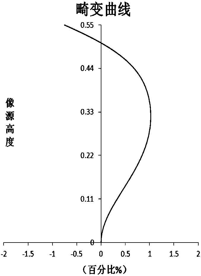
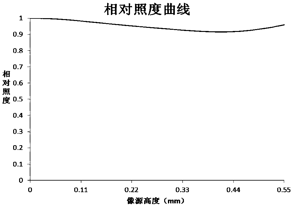
[0074] Refer to the following Figure 1 to Figure 2B A projection lens according to Embodiment 1 of the present application is described. figure 1 A schematic structural diagram of a projection lens according to Embodiment 1 of the present application is shown.
[0075] Such as figure 1 As shown, the projection lens according to the exemplary embodiment of the present application sequentially includes: a first lens E1 , a second lens E2 , a third lens E3 and a stop STO along the optical axis from the image source side to the imaging side.
[0076] The first lens E1 has a positive refractive power, its near image source side S1 is a convex surface, and its near image source side S2 is a concave surface; the second lens E2 has a negative refractive power, its near image source side S3 is a concave surface, and its near image source side S4 is a concave surface ; The third lens E3 has a positive refractive power, its side near the image source S5 is concave, and its side near t...
Embodiment 2
[0105] Refer to the following Figure 3 to Figure 4B A projection lens according to Embodiment 2 of the present application is described. In this embodiment and the following embodiments, for the sake of brevity, descriptions similar to those in Embodiment 1 will be omitted. image 3 A schematic structural diagram of a projection lens according to Embodiment 2 of the present application is shown.
[0106] Such as image 3As shown, the projection lens according to the exemplary embodiment of the present application sequentially includes: a first lens E1 , a second lens E2 , a third lens E3 and a stop STO along the optical axis from the image source side to the imaging side.
[0107] The first lens E1 has a positive refractive power, its near image source side S1 is a convex surface, and its near imaging side S2 is a convex surface; the second lens E2 has a negative refractive power, its near image source side S3 is a concave surface, and its near image source side S4 is a con...
Embodiment 3
[0121] Refer to the following Figure 5 to Figure 6B A projection lens according to Embodiment 3 of the present application is described. Figure 5 A schematic structural diagram of a projection lens according to Embodiment 3 of the present application is shown.
[0122] Such as Figure 5 As shown, the projection lens according to the exemplary embodiment of the present application sequentially includes: a first lens E1 , a second lens E2 , a third lens E3 and a stop STO along the optical axis from the image source side to the imaging side.
[0123] The first lens E1 has a positive refractive power, its near image source side S1 is a convex surface, and its near imaging side S2 is a convex surface; the second lens E2 has a negative refractive power, its near image source side S3 is a concave surface, and its near image source side S4 is a concave surface ; The third lens E3 has a positive refractive power, its side near the image source S5 is concave, and its side near the i...
PUM
 Abstract
Description
Claims
Application Information
 - R&D
- Intellectual Property
- Life Sciences
- Materials
- Tech Scout
- Unparalleled Data Quality
- Higher Quality Content
- 60% Fewer Hallucinations
Browse by: Latest US Patents, China's latest patents, Technical Efficacy Thesaurus, Application Domain, Technology Topic, Popular Technical Reports.
© 2025 PatSnap. All rights reserved.Legal|Privacy policy|Modern Slavery Act Transparency Statement|Sitemap|About US| Contact US: help@patsnap.com


