Pneumatic microdroplet jetting state control system and method based on machine vision

A droplet ejection and machine vision technology, applied in ejection devices and other directions, can solve problems such as reducing experimental efficiency, relying on operator experience and subjective judgment, increasing experimental complexity, etc., to achieve the effect of improving use efficiency.

Active Publication Date: 2018-07-20
BEIJING UNIV OF TECH
View PDF5 Cites 10 Cited by
  • Summary
  • Abstract
  • Description
  • Claims
  • Application Information

AI Technical Summary

Problems solved by technology

This not only increases the complexity of the experiment, reduces the efficiency of the experiment, but also relies too much on the operating experience and subjective judgment of the operator

Method used


Image

  • Pneumatic microdroplet jetting state control system and method based on machine vision
  • Pneumatic microdroplet jetting state control system and method based on machine vision
  • Pneumatic microdroplet jetting state control system and method based on machine vision

Examples


Embodiment 1

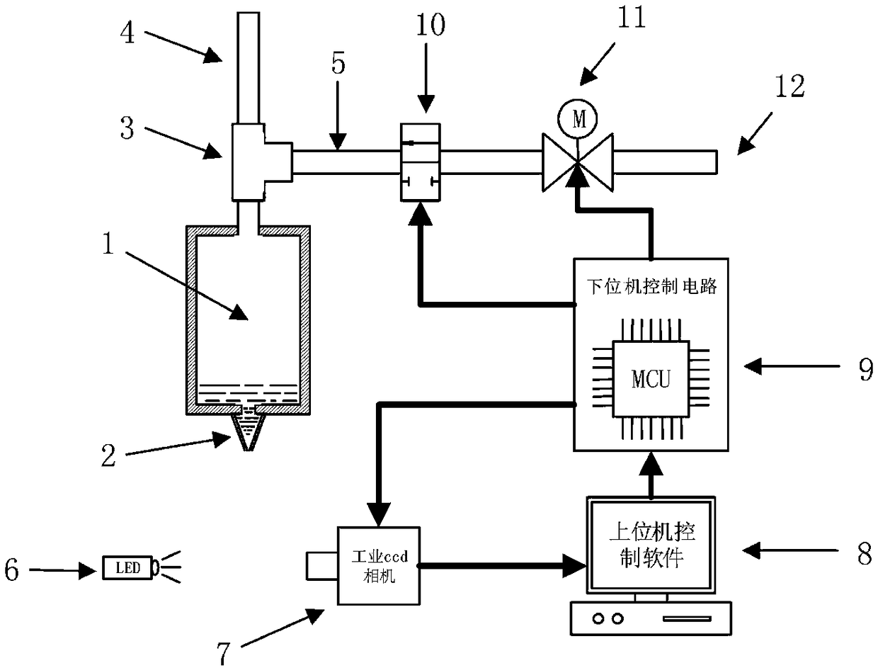
[0040]In this embodiment, the pneumatic droplet ejection device includes a droplet ejection system, a droplet observation system and a droplet control system. The control variable of the droplet control system is the conduction time t of the high-speed solenoid valve, and the air pressure P at the front end of the high-speed solenoid valve is constant.

[0041] Step 1, set the injection parameters of the device and start injection:

[0042] (1) Set the injection frequency of the device on the host computer control software to 80Hz, the conduction time t of the high-speed solenoid valve to 0us, the opening of the electric proportional valve to 25%, and the delay time of the industrial CCD camera to take pictures of 5000us and other parameters;

[0043] (2) Open the industrial CCD camera on the upper computer control software, open the serial communication interface to communicate with the lower computer control circuit, and send the above parameters to the lower computer contro...

Embodiment 2

[0060] In this embodiment, the pneumatic droplet ejection device includes a droplet ejection system, a droplet observation system and a droplet control system. The control variable of the droplet control system is the air pressure P at the front end of the high-speed solenoid valve. P is controlled by the opening of the electric proportional valve, and the conduction time t of the high-speed solenoid valve remains unchanged.

[0061] Step 1, set the injection parameters of the device and start injection:

[0062] (1) On the host computer control software, set parameters such as the injection frequency of the device to 80Hz, the conduction time t of the solenoid valve to 1000us, the opening of the electric proportional valve to 0%, and the delayed photo time of the industrial CCD camera to 5000us;

[0063] (2) Open the industrial CCD camera on the upper computer control software, open the serial communication interface to communicate with the lower computer control circuit, and...


PUM


Abstract

The invention discloses a pneumatic microdroplet jetting state control system and method based on machine vision, and belongs to the field of microdroplet jetting. By means of the method, the high speed solenoid valve breakover time t or the high speed solenoid valve front end air pressure P can be singly controlled, and single microdroplets can be stably jetted out in the initialized jetting andjetting process of the system. According to the system and method, a pneumatic microdroplet jetting device can automatically identify the microdroplet jetting state from shot microdroplet images in the initialized jetting and jetting process, the opening degree of an electric proportional valve is controlled to adjust the high speed solenoid valve front end air pressure P and the high speed solenoid valve breakover time t, and it can guarantee that the system can stably jet out single microdroplets all the time. The operation that an operator needs to judge the microdroplet jetting state according to the microdroplet images shot by a CCD camera in real time, the high speed solenoid valve front end air pressure P and the high speed solenoid valve breakover time t need to be manually adjusted is replaced, and the using efficiency of the device is improved.

Description

technical field [0001] The invention specifically relates to a pneumatic droplet spraying system, which can automatically adjust the controller in real time through the machine vision detection system to generate the spraying state of the droplet, so as to realize the function of stably spraying a single droplet during the initial spraying and spraying process of the system, The invention belongs to the technical field of droplet ejection. Background technique [0002] Droplet ejection is a technology in which an external force is used as a driving force to force a liquid to be ejected from a small hole in the form of a droplet. Common micro-droplet injection methods mainly include piezoelectric-driven injection, thermal bubble-driven injection, and air pressure-driven injection. Especially for sample application and 3D bioprinting in the field of biomedicine, in the actual operation of the piezoelectric drive nozzle, the setting of working parameters is more complicated, a...

Claims


Application Information

Patent Timeline
Patent Type & Authority Applications(China)
IPC IPC(8): B05B12/00B05B15/00
CPCB05B12/00B05B15/00
Inventor 王志海王飞
Owner BEIJING UNIV OF TECH
Why Eureka
Try Eureka