A passive compliant joint with variable stiffness based on elastic elements

An elastic element and joint technology, applied in the field of variable stiffness passively compliant joints, can solve problems such as poor dynamic performance and increase energy loss, and achieve the effects of reducing energy loss, increasing natural frequency, and increasing frequency bandwidth

Active Publication Date: 2021-01-29
HARBIN INST OF TECH
View PDF9 Cites 0 Cited by
  • Summary
  • Abstract
  • Description
  • Claims
  • Application Information

AI Technical Summary

Problems solved by technology

[0005] In order to solve the problems of fixed stiffness, poor dynamic performance and increased energy loss of the existing serial elastic actuators, the present invention further proposes a variable stiffness passive compliant joint based on elastic elements

Method used


Image

  • A passive compliant joint with variable stiffness based on elastic elements
  • A passive compliant joint with variable stiffness based on elastic elements
  • A passive compliant joint with variable stiffness based on elastic elements

Examples


specific Embodiment approach 1

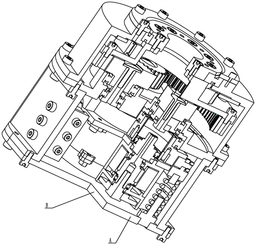
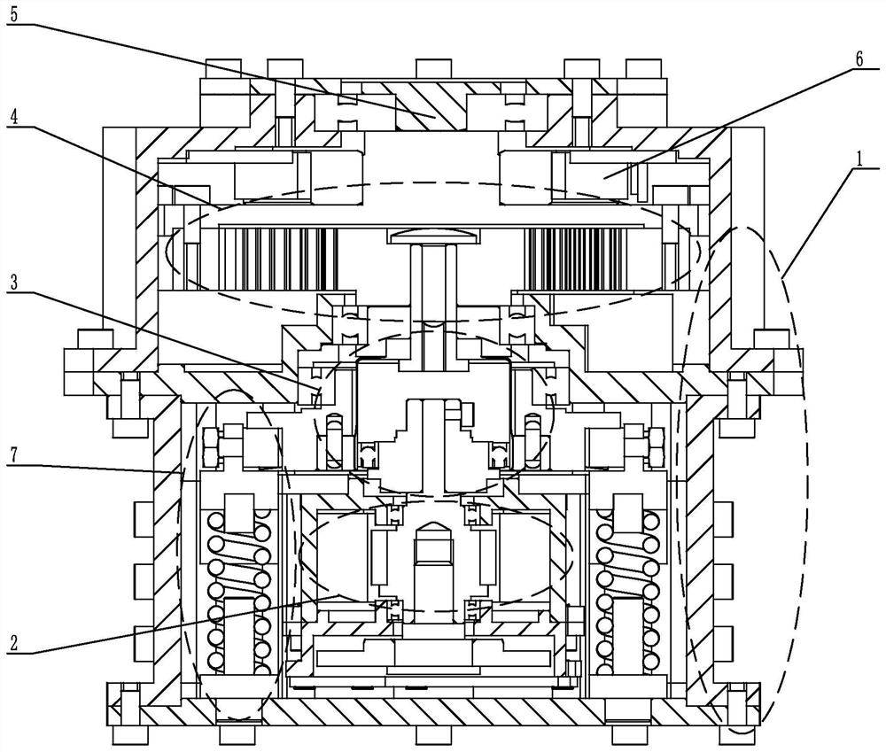
[0020] Specific implementation mode one: combine Figure 1 to Figure 5 Describe this embodiment. A variable stiffness passive compliant joint based on elastic elements in this embodiment includes a joint housing 1, a gear transmission mechanism 4, a joint output 5, a magnetic encoder 6 at the joint end, two joint motors 2, Two harmonic reducers 3 and two stiffness adjustment mechanisms 7, the joint motor 2 are symmetrically fixed inside the joint housing 1, the gear transmission mechanism 4 includes an output end and two input ends, and the motor shaft 204 of the joint motor 2 The harmonic reducer 3 is connected to the input end of the gear transmission mechanism 4, the output end of the gear transmission mechanism 4 is connected to the joint output 5, the magnetic encoder 6 at the joint end is connected to the gear transmission mechanism 4, and both sides of the harmonic reducer 3 A stiffness adjustment mechanism 7 is symmetrically provided.

specific Embodiment approach 2

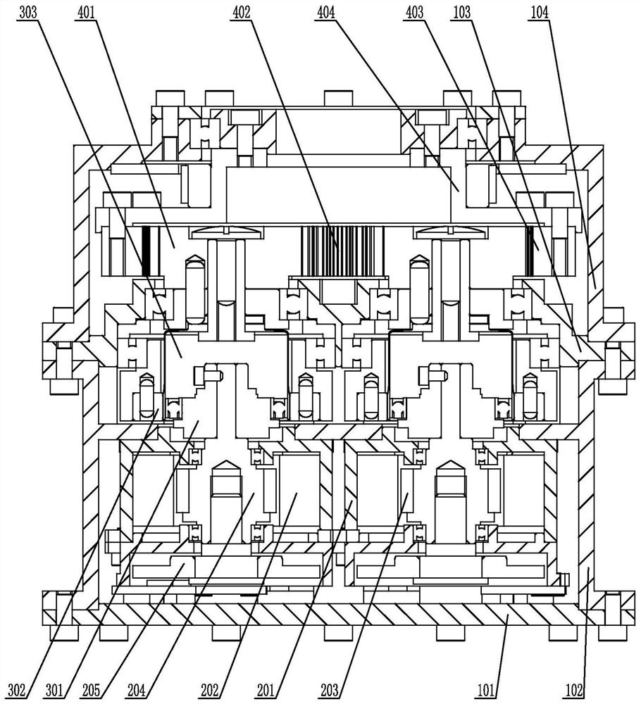
[0021] Specific implementation mode two: combination Figure 1 to Figure 4 To describe this embodiment, the joint motor 2 in this embodiment further includes a motor housing 201 , and the motor housing 201 is fixedly connected to the joint housing 1 . Other compositions and connection methods are the same as those in Embodiment 1.

specific Embodiment approach 3

[0022] Specific implementation mode three: combination Figure 1 to Figure 4 Describe this embodiment, the joint motor 2 described in this embodiment also includes a stator 202, a rotor 203 and a motor end magnetic encoder 205, the stator 202 is fixed inside the motor housing 201, the rotor 203 is arranged inside the stator 202, and the rotor 203 Rotating relative to the stator 202 , the motor end magnetic encoder 205 is arranged inside the motor housing 201 and connected to the motor shaft 204 . Other compositions and connection methods are the same as those in the second embodiment.


PUM


Abstract

The invention provides a variable rigidity passive flexible joint based on elastic elements and relates to the robot technology. Through the variable rigidity passive flexible joint based on the elastic elements, the problems that existing series elastic actuators are fixed in rigidity and poor in dynamic performance and energy consumption is increased can be solved. The variable rigidity passiveflexible joint based on the elastic elements comprises a joint shell, a gear transmission mechanism, a joint output, a joint end magnetic encoder, two joint motors, two harmonic reducers and two rigidity adjusting mechanisms. The joint motors are symmetrically and fixedly connected to the interior of the joint shell. The gear transmission mechanism comprises an output end and an input end. Motor shafts of the joint motors are connected with the input end of the gear transmission mechanism through the harmonic reducers. The output end of the gear transmission mechanism is connected with the joint output. The joint end magnetic encoder is connected with the gear transmission mechanism. The rigidity adjusting mechanisms are symmetrically arranged on the two sides of the harmonic reducers. Thevariable rigidity passive flexible joint based on the elastic elements is applied to a flexible joint robot.

Description

technical field [0001] The invention relates to robot technology, in particular to a passive compliant joint with variable stiffness based on elastic elements. Background technique [0002] In order to ensure the speed and position accuracy, traditional industrial robots often adopt the "rigid design, control to achieve safety" mode, and move according to the established trajectory in a structured environment to complete specific tasks. Rigid design methods are often used for joints. With more and more opportunities for robots to come into contact with people during work, there is an urgent need for a robot system that can be used in an environment that cooperates with people, is friendly to the environment, and does not cause harm to the external environment. [0003] The flexible joint robot adopts the mode of "design to achieve safety, control to improve performance", and a passive and compliant structure is integrated inside the joint. When colliding with the external e...

Claims


Application Information

Patent Timeline
Patent Type & Authority Patents(China)
IPC IPC(8): B25J17/02
CPCB25J17/0208B25J17/0266
Inventor 刘宏崔士鹏刘伊威孙永军任义
Owner HARBIN INST OF TECH
Why Eureka
Try Eureka