Vacuum tank detection anti-explosion device

An explosion-proof device and vacuum tank technology, applied in the layout of reservoirs, brake safety systems, etc., can solve the problems of complex devices, high production costs of explosion-proof detection devices, and low safety performance of pressure detection, and achieve convenient operation, simple structure, Check the effect of high safety performance

Inactive Publication Date: 2018-07-20
芜湖捷欧汽车部件股份有限公司
View PDF9 Cites 1 Cited by
  • Summary
  • Abstract
  • Description
  • Claims
  • Application Information

AI Technical Summary

Problems solved by technology

[0004] The purpose of the present invention is to overcome the deficiencies of the prior art and provide a vacuum tank detection explosion-proof device to solve the technical problems of high production cost, complex device and low pressure detection safety performance of the explosion-proof detection device in the prior art

Method used


Image

  • Vacuum tank detection anti-explosion device
  • Vacuum tank detection anti-explosion device
  • Vacuum tank detection anti-explosion device

Examples


Embodiment 1

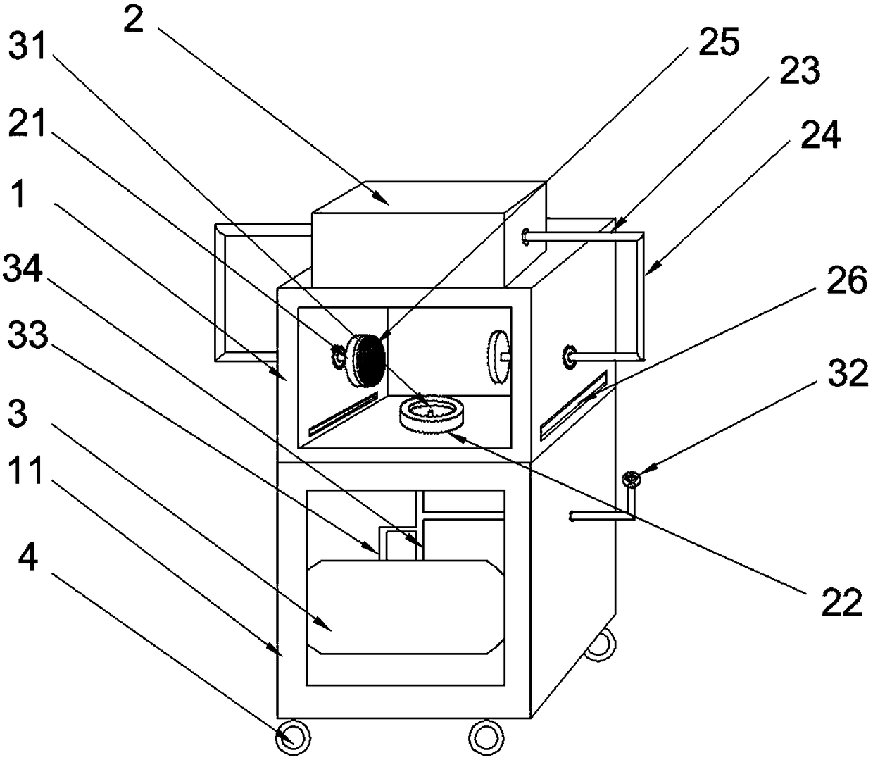
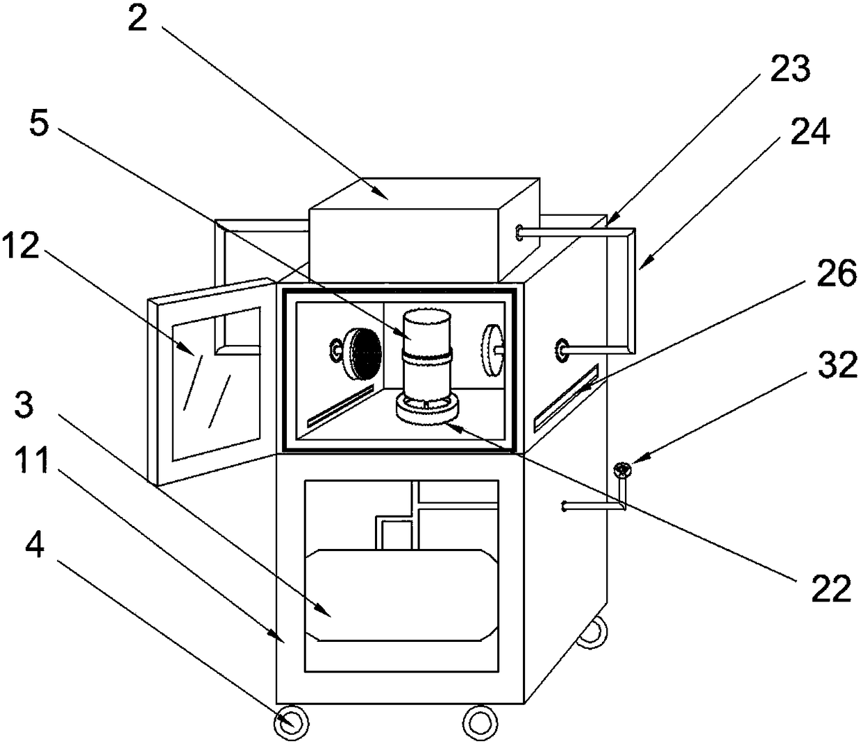
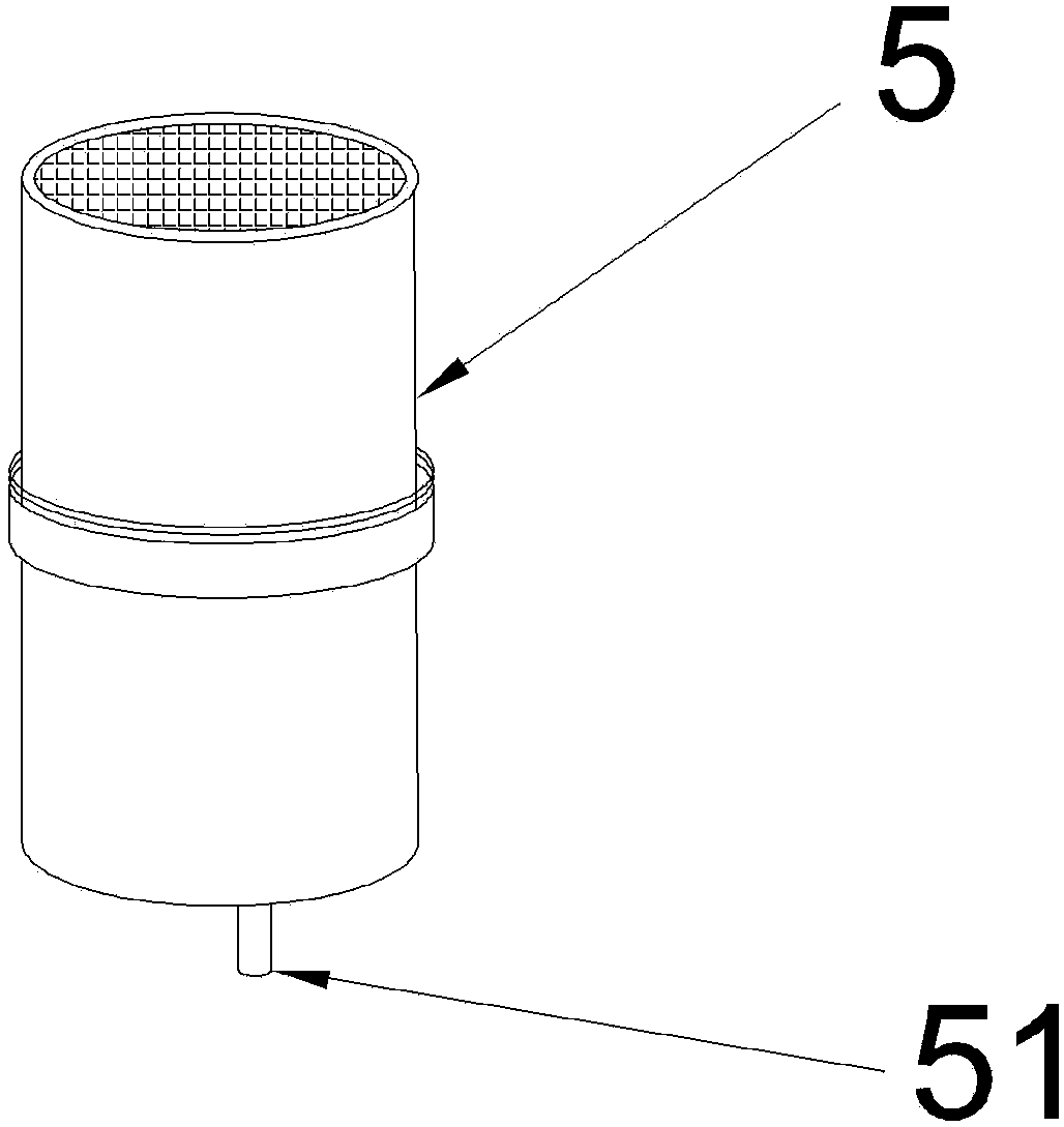
[0020] Embodiment 1 discloses a vacuum tank detection explosion-proof device, such as Figure 1-3 As shown, it includes a box frame, a vacuum tank fixing device and an air pump 3. The vacuum tank fixing device is fixedly installed on the box frame, and the air pressure pump 3 is arranged in the inner cavity of the box frame. During work, the vacuum tank 5 is carried out by the vacuum tank fixing device. Fixed, the joint 31 of the air pump 3 is connected with the air inlet 51 of the vacuum tank 5, and the pressure of the vacuum tank 5 is detected by the air pump 3. Wherein the box frame in the present embodiment is formed by connecting the upper box body 1 and the lower box body 11; Fixedly installed on the top of the upper box body 1, a pair of fixed plates 21 are arranged relatively parallel to the inner cavity of the upper box body 1, and the pair of fixed plates 21 are respectively connected to the piston rods 23 at both ends of the double-rod hydraulic cylinder 2 through L...

Embodiment 2

[0022] Embodiment 2 discloses a vacuum tank detection explosion-proof device, including a box frame, a vacuum tank fixing device and an air pressure pump 3, the vacuum tank fixing device is fixedly installed on the box frame, and the air pressure pump 3 is arranged in the inner cavity of the box frame. , the vacuum tank 5 is fixed by the vacuum tank fixing device, the joint 31 of the air pump 3 is connected with the air inlet 51 of the vacuum tank 5, and the pressure of the vacuum tank 5 is detected by the air pump 3. Wherein the box frame in the present embodiment is formed by connecting the upper box body 1 and the lower box body 11; Fixedly installed on the top of the upper box body 1, a pair of fixed plates 21 are arranged relatively parallel to the inner cavity of the upper box body 1, and the pair of fixed plates 21 are respectively connected to the piston rods 23 at both ends of the double-rod hydraulic cylinder 2 through L-shaped connecting rods 24 is fixedly connected...


PUM


Abstract

The invention discloses a vacuum tank detection anti-explosion device, and belongs to a plastic tank pressure detecting device. The vacuum tank detection anti-explosion device comprises a box frame, avacuum tank fixing device and a pneumatic pump. The vacuum tank fixing device is fixedly installed on the box frame. The pneumatic pump is arranged in an inner cavity of the box frame. During working, a vacuum tank is fixed by the vacuum tank fixing device, a joint of the pneumatic pump is connected with an air inlet hole of the vacuum tank, so that a pressure test of the vacuum tank is realizedby the pneumatic pump. According to the vacuum tank detection anti-explosion device, the technical problem that an existing safety detection and protection device is high in the cost, complex in the structure and not suitable for production needs of small and medium sized car enterprises and part manufacturers are solved. Compared with an existing air pressure anti-explosion detection device, thevacuum tank detection anti-explosion device has the characteristics of simple structure, convenient operation, high detection safety performance, high detection precision, and simultaneous detection of two kinds of testing items including positive pressure and negative pressure, and at the same time, an inspector can observe test results at a close range, and popularization and use for the small and medium sized part manufacturers are facilitated.

Description

technical field [0001] The invention relates to vacuum tank detection equipment, in particular to an explosion-proof device for vacuum tank detection. Background technique [0002] For a long time, fuel vehicles have been the main force in the automotive industry. However, with the increasing environmental pollution and the gradual depletion of oil resources, new energy vehicles have become a new growth point in the auto market. Promoting the transition from high-pollution and high-emission traditional fuel vehicles to zero-emission or low-emission new energy vehicles is the only way for the automotive industry. Traditional fuel vehicles mainly use the rotation of the engine to continuously pump the vacuum to ensure a certain amount of brake power, and the operation method is more sensitive. In existing electric vehicles, the engine has been replaced by an electric motor, and the engine in a hybrid electric vehicle is not always working, and the electric motor cannot alway...

Claims


Application Information

Patent Timeline
Patent Type & Authority Applications(China)
IPC IPC(8): B60T17/22B60T17/06
CPCB60T17/06B60T17/22
Inventor 邵登马旭王丽张浩周孙进
Owner 芜湖捷欧汽车部件股份有限公司
Why Eureka
Try Eureka