Ultra high strength low temperature ductile iron casting for wind turbine generator and manufacturing method thereof

An ultra-high-strength, wind turbine technology, applied in the direction of improving process efficiency, can solve the problems of qualified low-temperature impact energy at the strength level, and the chemical composition and process angle cannot be improved, and achieve the effect of improving the strength index and lightweight design.

Inactive Publication Date: 2018-07-20
XINJIANG GOLDWIND SCI & TECH +1
View PDF3 Cites 9 Cited by
  • Summary
  • Abstract
  • Description
  • Claims
  • Application Information

AI Technical Summary

Problems solved by technology

Although the patent application proposes ideas such as increasing the number of graphite balls and refining graphite balls, it is impossible to improve the strength level while ensuring qualified low-temperature impact energy from the perspective of chemical composition and technology.

Method used


Image

  • Ultra high strength low temperature ductile iron casting for wind turbine generator and manufacturing method thereof
  • Ultra high strength low temperature ductile iron casting for wind turbine generator and manufacturing method thereof
  • Ultra high strength low temperature ductile iron casting for wind turbine generator and manufacturing method thereof

Examples


Embodiment 1

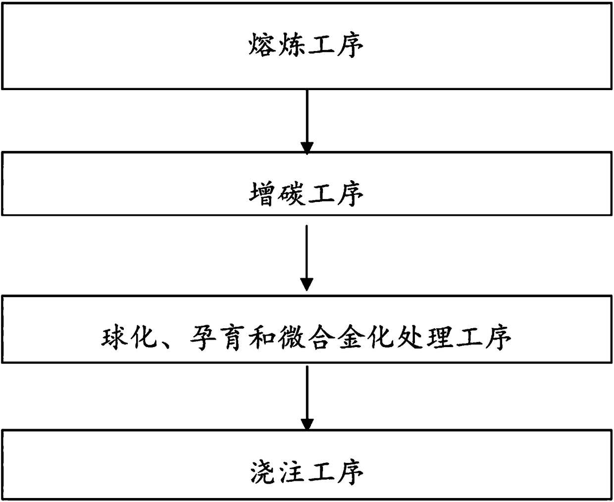
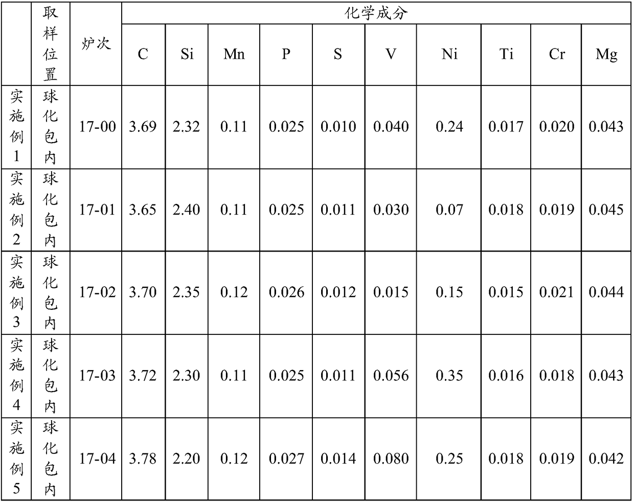
[0058] A 10T intermediate frequency furnace is used to smelt pig iron, recycled material and scrap steel. The smelting temperature is 1430°C. At this temperature, the molten iron is carburized in the electric furnace. Lay the inoculant on one side of the dam in the 1T spheroidizing bag, and lay the nodulizer, recarburizer, V in the microalloy and Ni in the microalloy on the other side of the dam from bottom to top, and then cover it with cast iron shavings On Ni in the microalloy, the covering thickness is 6-10mm. Add molten iron into the spheroidizing bag from the side of the spheroidizing bag where the inoculant is laid, wherein the additions of the spheroidizing agent and the inoculant are 1.0wt% and 0.4wt% respectively, and the addition of V and Ni in the microalloy The amount is shown in Table 2. The pouring process adopts the secondary inoculation method, and the addition amount of the flow inoculant is 0.15wt%. The components of the obtained ductile iron piece include...

Embodiment 2- Embodiment 5

[0060] Ductile iron pieces were prepared according to the method of Example 1 except that the composition of molten iron, nodulizer, inoculant, and flow inoculant were added in different amounts. Table 2 and Table 3 show the component content of molten iron in the spheroidizing ladle of Example 2-Example 5, the addition amount of nodulizer, inoculant and flow inoculant. The mechanical properties of the prepared ductile iron pieces are shown in Table 4.

[0061] Table 2

[0062]

[0063] table 3

[0064]

Nodulizer (wt%)

Inoculants (wt%)

Flowing inoculant (wt%)

Example 1

1.00

0.40

0.15

Example 2

1.10

0.45

0.10

Example 3

1.20

0.48

0.13

Example 4

1.15

0.60

0.20

Example 5

1.17

0.50

0.18

[0065] Table 4

[0066]

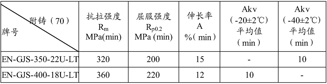
[0067] It can be seen from the above examples that the tensile strength of the ductile iron parts prepared by the method of the present invention is greater ...


PUM

PropertyMeasurementUnit
yield strengthaaaaaaaaaa
thicknessaaaaaaaaaa
tensile strengthaaaaaaaaaa

Abstract

The invention discloses an ultra high strength low temperature ductile iron casting for a wind turbine generator and a manufacturing method thereof. The ductile iron casting comprises, by weight, 3.6-3.8% of C, 2.1-2.5% of Si, no more than 0.15% of Mn, no more than 0.027% of P, 0.008-0.014% of S, 0.01-0.10% of V, 0.05-0.40% of Ni, no more than 0.020% of Ti, no more than 0.025% of Cr, 0.035-0.045%of Mg residual, and the balance Fe and unavoidable impurities. The tensile strength of the ductile iron casting Rm is larger than or equal to 400MPa, the yield strength Rp0.2 is larger than or equal to 260MPa and the impact energy alpha k is larger than or equal to 10J at minus 20 DEG C. The proportional relationship of the chemical composition of the ductile iron casting is determined according to CE, Rm and/or alpha k. The ultra high strength low temperature ductile iron casting for the wind turbine generator greatly improves the strength index under the situation of ensuring the low temperature impact energy at minus 20 DEG C.

Description

technical field [0001] The invention relates to an ultra-high-strength low-temperature ductile iron part and a manufacturing method thereof, in particular to an ultra-high-strength low-temperature ductile iron part for a wind turbine and a manufacturing method thereof. Background technique [0002] At present, castings for wind power use EN-GJS-400-18U-LT material grade or EN-GJS-350-22U-LT material grade specified in EN-1563 standard. When the size of the attached casting test block is 70×70×170mm, the properties of EN-GJS-400-18U-LT material grade and EN-GJS-350-22U-LT material grade are shown in Table 1. However, neither of these two materials can meet the lightweight design requirements of castings for wind turbines. With the increase in size of wind turbines, wind power castings need to choose higher strength low-temperature ductile iron (abbreviation for "ductile iron") to achieve lightweight casting design. [0003] Table 1 [0004] [0005] At present, the rese...

Claims


Application Information

Patent Timeline
Patent Type & Authority Applications(China)
IPC IPC(8): C22C37/04C22C37/08C22C37/10C22C33/10C21C1/10
CPCC21C1/105C22C33/10C22C37/04C22C37/08C22C37/10Y02P10/20
Inventor 万曙雄王星陈玉芳王美喜
Owner XINJIANG GOLDWIND SCI & TECH
Why Eureka
Try Eureka