LED light bar clamped and welded between double PCBs and light bar screen

A light bar and strip technology, which is applied in the structural connection of printed circuits, printed circuits connected with non-printed electrical components, printed circuits, etc., can solve the problems of increasing cost and manufacturing difficulty, and reducing the hollow area of ​​light bar screens. , to achieve the effect of enhancing the bending resistance, increasing the moment of inertia of the section, and increasing the hollow area

Pending Publication Date: 2018-07-20
潘尚法
View PDF7 Cites 1 Cited by
  • Summary
  • Abstract
  • Description
  • Claims
  • Application Information

AI Technical Summary

Problems solved by technology

This type of existing technology is difficult to make narrow light strips, thus reducing the hollow area of ​​the light bar screen. In order not to expose the electronic components, the light bar can only be covered with a casing, which increases the cost and difficulty of production.
Therefore, there is still room for improvement in the prior art

Method used


Image

  • LED light bar clamped and welded between double PCBs and light bar screen
  • LED light bar clamped and welded between double PCBs and light bar screen
  • LED light bar clamped and welded between double PCBs and light bar screen

Examples


Embodiment Construction

[0017] In order to make the present invention more comprehensible, preferred embodiments are described below with accompanying drawings. It should be noted that the embodiments and the features in the embodiments can be combined with each other under the condition of no conflict.

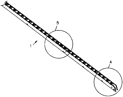
[0018] figure 1 It is a structural schematic diagram of an embodiment of the present invention. See figure 1 , Light bar 1 is a light bar with double PCB clip-welded LEDs. Since the light bar is relatively long, there are more LEDs installed, and the structure is similar, so figure 1 Only a section of the light bar is shown.

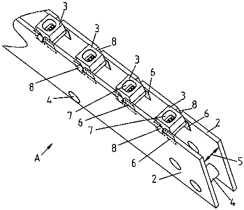
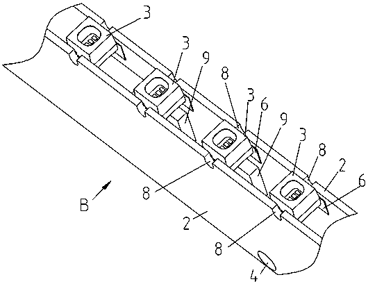
[0019] figure 2 with image 3 respectively figure 1 Schematic diagram of the structure of part A and part B. See figure 2 with image 3 , the two strip PCBs 2 are respectively provided with pads 6 for soldering LED side pins ( figure 2 Indicated by a dotted line on the front PCB), and according to the requirements of the light bar, the electronic components 9 are ...


PUM


Abstract

The invention provides an LED light bar clamped and welded between double PCBs and a light bar screen composed of the LED light bar. The LED light bar is composed of two bar-shaped PCBs with or without electronic components, SMD packaged LEDs and supporting and connecting pieces; the sides with the electronic components of the two bar-shaped PCBs face the inward and are opposite to each other, arealigned in one edge, and are fixed by the supporting and connecting pieces; an interval for clamping and welding pins in the side surface of the LED is left between the PCBs, each side-surface pin ofthe LED is welded to a pad close to the aligned edge of each PCB, the light bar is formed, and the light bars are combined to form the light bar screen. The LED is welded into the interval between the bar-shaped PCBs from the side surface, the light bar is narrowed, the hollow area is increased, and the hollow area in a position without LED in the internal between the PCBs is also increased; thesides welded with the electronic components of the bar-shaped PCBs are inwards and opposite to each other, so that the electronic components are hidden in the interval between the PCBs, and the electronic components except the light surface are not exposed; and the LED is clamped and welded between the PCBs in the hollowed way, the sectional inertia moment of the light bar is increased, and the bending resistance of the light bar is improved greatly.

Description

technical field [0001] The invention relates to a structure for making a light bar by using LEDs, in particular to a light bar structure using two PCBs to clamp and weld LEDs, and a light bar display screen (light bar screen) formed therefrom. Background technique [0002] The main technical goal of the light bar screen is to pursue a higher transmittance under a given LED (light-emitting diode) density (ie, pixel density), that is, to pursue a larger hollow area on the light bar screen, and at the same time for safety, reliability and Beautiful, it is best not to expose electronic components (except for the LED lamp surface), and the production is simple and convenient. In the prior art, LEDs are welded and mounted on a strip-shaped PCB (printed circuit board) to form a light strip, and then the light strips are arranged and assembled into a light strip screen. This type of existing technology is difficult to make a narrow light bar, thus reducing the hollow area of ​​the ...

Claims


Application Information

Patent Timeline
Patent Type & Authority Applications(China)
IPC IPC(8): H05K1/18H05K1/14H05K3/34
CPCH05K1/144H05K1/181H05K3/341H05K2201/10106
Inventor 潘尚法
Owner 潘尚法
Why Eureka
Try Eureka