Glove stacking and counting machine

A glove and stacking technology, which is applied in the field of glove stacking and counting machines, can solve the problems of high maintenance of finished products, high frequency of pneumatic control, and impact on glove packaging, and achieve the effects of convenient packaging, neat stacking, and accurate quantities

Pending Publication Date: 2018-07-24
淄博荣琦自动化科技有限公司
View PDF0 Cites 5 Cited by
  • Summary
  • Abstract
  • Description
  • Claims
  • Application Information

AI Technical Summary

Problems solved by technology

However, due to the softness of plastic gloves and the different quality of different gloves, it is impossible to ensure that the gloves sent to the transfer box are stacked neatly, which affects the subsequent packaging of the gloves, and the robot cannot smoothly send the gloves into the packaging box. , the failure rate is high, which affects the production efficiency of gloves
[0004] There are two main types of counting machines currently in existence: one type rolls the glove down with a roller, the glove runs on the belt, and when the glove is sucked to the position of the material box by the suction cup, the glove is blown to the material box by blowing air. The shortcomings of the machine are: 1. The adsorption effect is not good, and it cannot guarantee 100% adsorption of gloves; 2. It is difficult to control the effect by blowing down the gloves; 3. It consumes a lot of compressed air and vacuum energy
Another type of gloves is picked up by pneumatic grippers after demoulding and then rotated to the conveyor belt. The disadvantages of this type of counting machine are: 1. The frequency of pneumatic control is very high, the replacement cycle of pneumatic components is very short, and the maintenance of finished products is high; 2. The way of gripping and throwing the gloves with the claws is very unstable, and the gloves are easily thrown to the ground, causing pollution to the gloves

Method used


Image

  • Glove stacking and counting machine
  • Glove stacking and counting machine
  • Glove stacking and counting machine

Examples


Embodiment 1

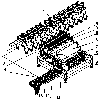
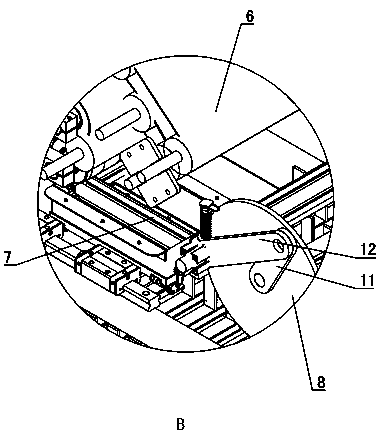
[0038] Such as Figure 1~3 As shown: the transfer conveyor belt 5 and the clamping conveyor mechanism 6 are installed on the frame 10, the transfer conveyor belt 5 is arranged horizontally, the clamping conveyor mechanism 6 is arranged at the output end of the transfer conveyor belt 5, and the stacking bin 7 is slidably installed on the On the frame 10, and the stacking bin 7 is arranged directly below the output end of the clamping conveying mechanism 6 .

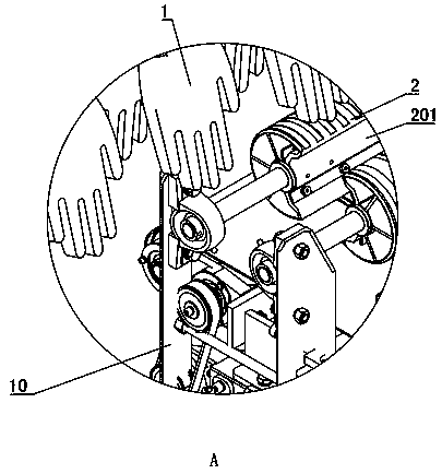
[0039] Rotate on the frame 10 and be equipped with horizontal pick-up roller 2, pick-up roller 2 has two, two pick-up rollers 2 are parallel and set at intervals, the axis of pick-up roller 2 is perpendicular to the conveying direction of transfer conveyer belt 5, two Two picking rollers 2 are arranged at intervals directly above the input end of the transfer conveyor belt 5 . A plurality of grooves are arranged at intervals around the sides of the two picking rollers 2 , thereby increasing the friction between the pickin...

Embodiment 2

[0055] The difference between Embodiment 2 and Embodiment 1 is that the clamping and conveying mechanism 6 is a clamping manipulator, and the clamping manipulator clamps and stacks the gloves on the transfer conveyor belt 5 in the stacking bin 7, thereby completing the stacking of gloves .

Embodiment 3

[0057] Such as Figure 8 As shown: the difference between embodiment 3 and embodiment 1 is that: the upper side of the two output conveyor belts 13 and the converging conveyor belt 19 is provided with a gantry manipulator, and the gantry manipulator will converge the gloves on the two output conveyor belts 13 to the converging conveyor belt 19, thereby completing the delivery of gloves.

[0058] The gantry manipulator comprises a gantry frame and two grippers 24 installed on the crossbeam of the gantry frame 25. Two translation motors 26 are installed on the crossbeam of the gantry frame 25. Gears are installed on the output shaft of each translation motor 26, and the crossbeam A rack that meshes with two gears simultaneously is installed on the top, thereby realizing the translation of two translation motors 26 . A lift cylinder is installed on each translation motor 26, and a swing cylinder 23 is installed on the piston rod of the lift cylinder, and the jaws 24 are installe...


PUM


Abstract

The invention discloses a glove stacking and counting machine and belongs to the technical field of glove production equipment. The glove stacking and counting machine is characterized in that the glove stacking and counting machine comprises a transferring conveying belt (5), a stacking bin (7) and a clamping conveying mechanism (6), wherein the stacking bin (7) is arranged at the output end of the transferring conveying belt (5), and the clamping conveying mechanism (6) is arranged between the transferring conveying belt (5) and the stacking bin (7); the stacking bin (7) is arranged at the lower side of the output end of the clamping conveying mechanism (6) in a sliding manner; the stacking bin (7) is connected with a power mechanism, wherein the stacking bin (7) is pushed by the power mechanism to perform reciprocating motion; the motion direction of the stacking bin (7) is parallel with the conveying direction of the transferring conveying belt (5); and a glove detection module isarranged at the side of the transferring conveying belt (5). By means of the transferring conveying belt of the glove stacking and counting machine, gloves taken off a hand mold can be conveyed to theclamping conveying mechanism; the clamping conveying mechanism clamp the gloves and is matched with the stacking bin, so that the gloves are gradually and flatly put into the stacking bin from one side; the stacking bin performs reciprocating motion; and it is guaranteed that the gloves are stacked orderly in the stacking bin.

Description

technical field [0001] A glove stacking and counting machine belongs to the technical field of glove production equipment. Background technique [0002] At present, the plastic glove production line mainly includes PVC, nitrile, latex gloves and other types. The glove production line has two rows of hand molds (commonly known as one-hand mold line) or four rows of hand molds (commonly known as two-hand mold line) for continuous production, and the operating speed is 120~160 pieces / min. [0003] The glove production process should go through cyclic hand mold dipping, glove drying and molding, and glove half-demolding. There are several processes such as glove removal and packaging. At present, after the gloves are half-off from the demoulding machine, they are taken off by the pick-up roller, and then sent to the transfer box by the conveyor belt, and the gloves are counted before delivery. However, due to the softness of plastic gloves and the different quality of differe...

Claims


Application Information

Patent Timeline
Patent Type & Authority Applications(China)
IPC IPC(8): B65B35/44B65B35/50B65B63/04B65B57/10
CPCB65B35/44B65B35/50B65B57/10B65B63/045
Inventor 耿世和赵畔良
Owner 淄博荣琦自动化科技有限公司
Why Eureka
Try Eureka