

Non-conventional winding system for high-multiplying-power bridge crane
A technology of large magnification and bridge crane, applied in the direction of load hanging components, transportation and packaging, can solve problems such as poor economy and rationality, aggravate wire ropes, and difficult layout, improve safety and reliability, and improve wire rope life. , the effect of ensuring the safety of the organization
- Summary
- Abstract
- Description
- Claims
- Application Information
AI Technical Summary
Problems solved by technology
Method used
Image

Examples
Embodiment Construction
[0032] The present invention is further described below in conjunction with accompanying drawing and embodiment:
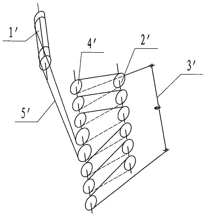
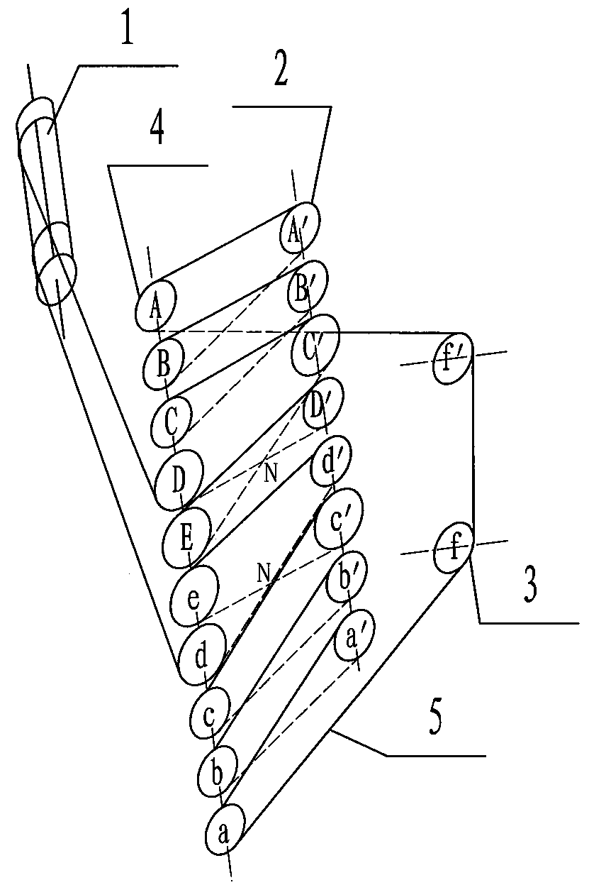
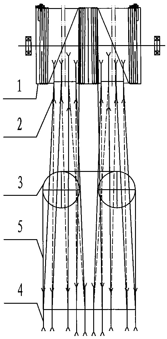
[0033] Such as Figure 2 to Figure 6 As shown, the unconventional winding system of the present invention is introduced as a representative of the winding system of the 200t lifting mechanism with a 10-fold ratio:
[0034] The unconventional winding system for a large-magnification bridge machine of the present invention includes a reel 1 arranged from top to bottom, a fixed pulley block 2, a balance pulley block 3, a movable pulley block 4, and a winding system that connects the above-mentioned components as a whole. Steel wire rope 5; the wire rope 5's wire rope 5 is fixed on both sides of the reel 1 at the end of the wire rope 5, and the rope outlet section of the wire rope 5 is wound around the movable pulley block 4 and the fixed pulley block 2 in a staggered manner. The rope-receiving pulley combination of the steel wire rope 5, the rope-receiving section o...
PUM
 Abstract
Description
Claims
Application Information