
Self-operated temperature control valve detection device and detection method

A self-operated temperature control valve and detection device technology, applied in the field of gas, can solve the problems of low work efficiency, time-consuming and labor-intensive, and potential safety hazards, and achieve the effects of less energy consumption, high work efficiency, and less manual workload.

Inactive Publication Date: 2018-07-24
SHANDONG IRON & STEEL CO LTD
View PDF8 Cites 1 Cited by
  • Summary
  • Abstract
  • Description
  • Claims
  • Application Information

AI Technical Summary

Problems solved by technology

Since the condensed water contains harmful substances such as gas ash and acidic chemicals, if the temperature control valve is used in this environment for a long time, it is easy to cause failures such as valve core corrosion, hydraulic oil leakage, and spring failure.
In the past, when a valve failed, it had to be returned to the factory for repair, which was time-consuming and labor-intensive, and at the same time, it was impossible to control the whole process of the repaired valve, and its performance could not be checked and accepted in time after repair, posing a safety hazard; When conducting sensitivity experiments on temperature control valves that have not failed, it is necessary to conduct online experiments on the drainer, which requires the drainer to be steamed, and due to limited conditions, the experiment can only be carried out on a single unit, resulting in low work efficiency and manual work. and high energy consumption

Method used


Image

  • Self-operated temperature control valve detection device and detection method
  • Self-operated temperature control valve detection device and detection method
  • Self-operated temperature control valve detection device and detection method

Examples


Embodiment Construction

[0019] In order to make the purpose, technical solution and advantages of the present invention clearer, the technical solution of the present invention will be clearly and completely described below in conjunction with specific embodiments of the present invention and corresponding drawings. Apparently, the described embodiments are only some of the embodiments of the present invention, but not all of them. Based on the embodiments of the present invention, all other embodiments obtained by persons of ordinary skill in the art without making creative efforts fall within the protection scope of the present invention.

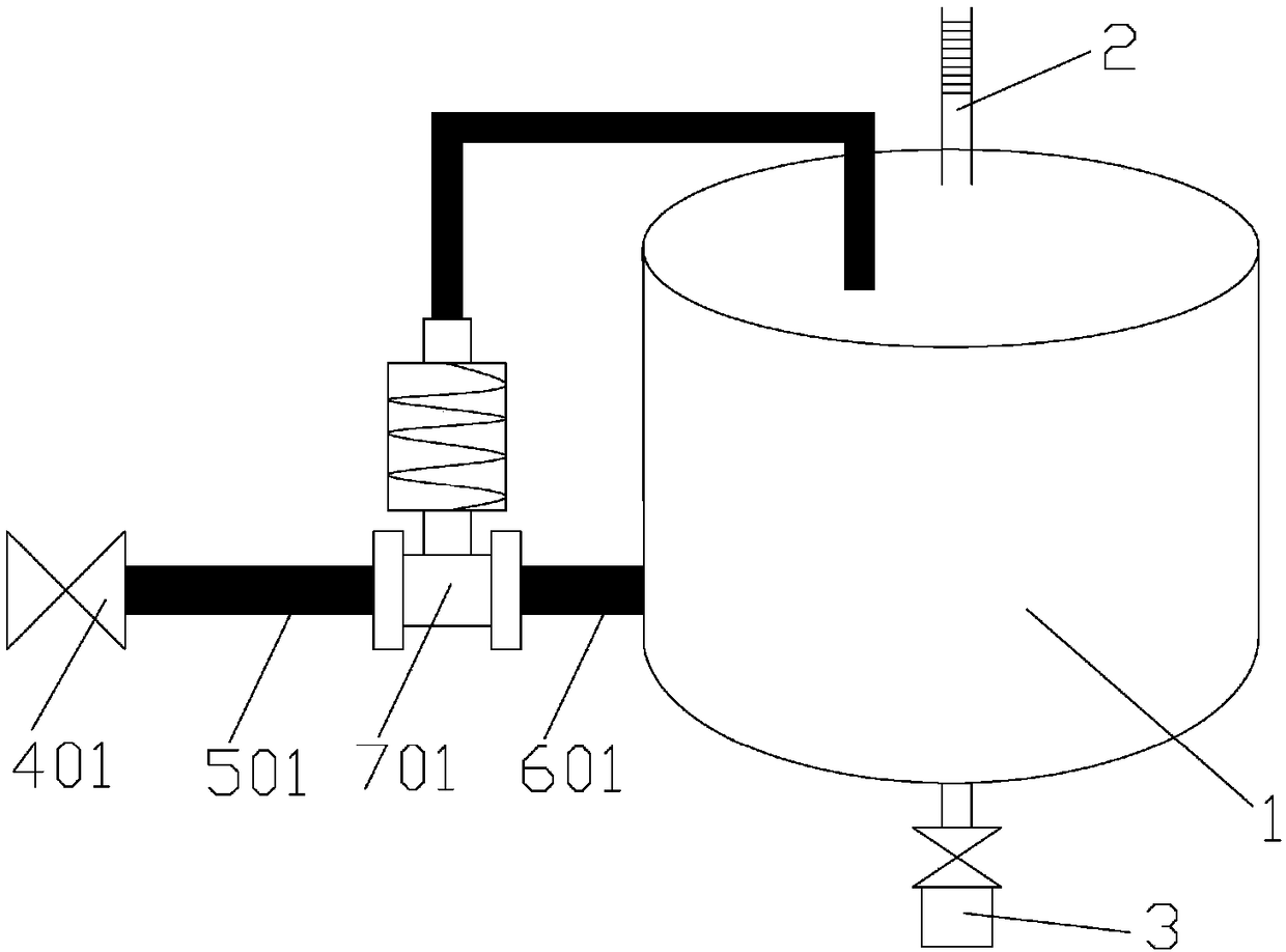
[0020] figure 1 It is a schematic structural diagram of a self-operated temperature control valve detection device according to Embodiment 1 of the present invention. Such as figure 1 As shown, the self-operated temperature control valve detection device of this embodiment is suitable for fault elimination and sensitivity experiments of a single self-operated ...


PUM


Abstract

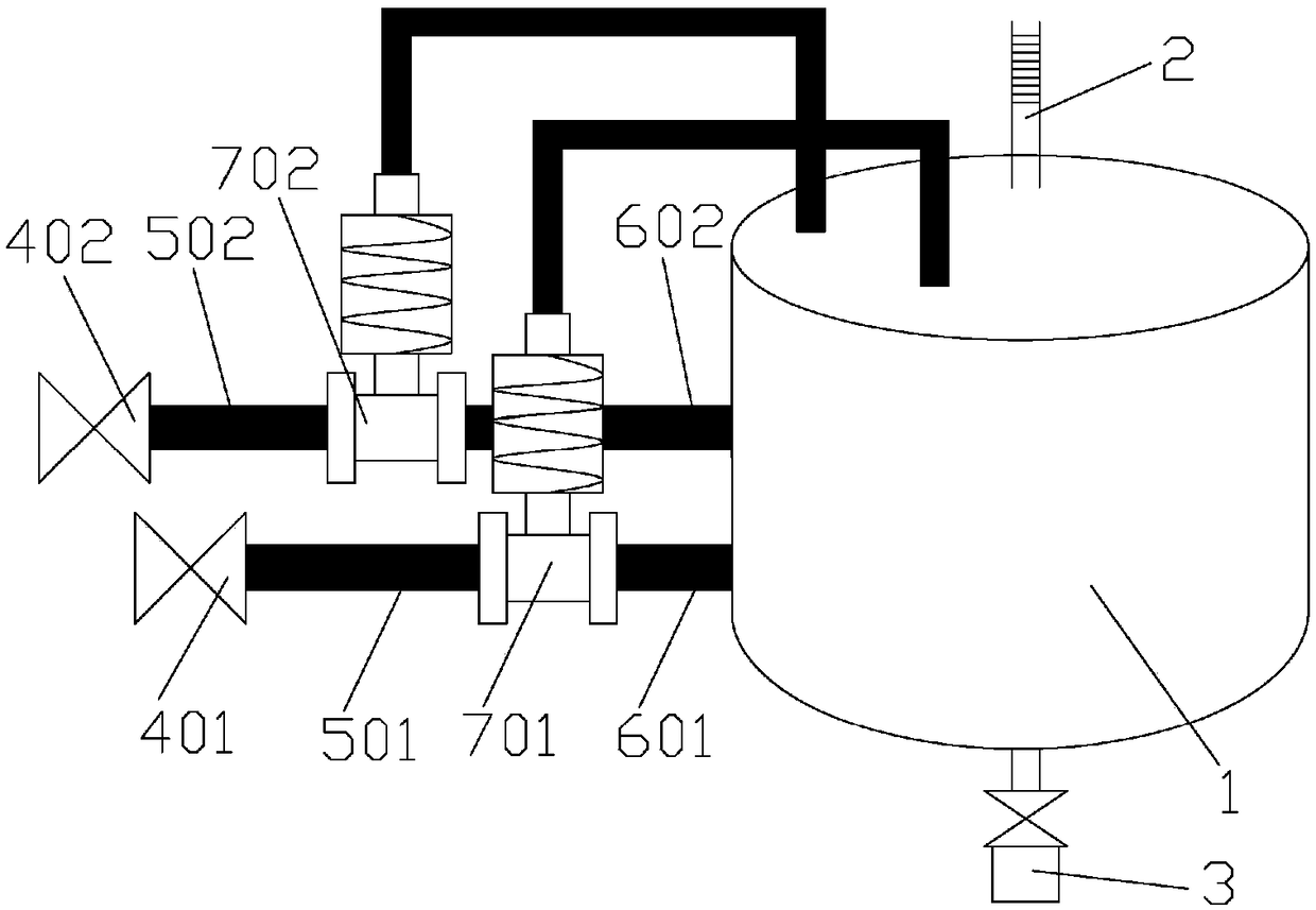
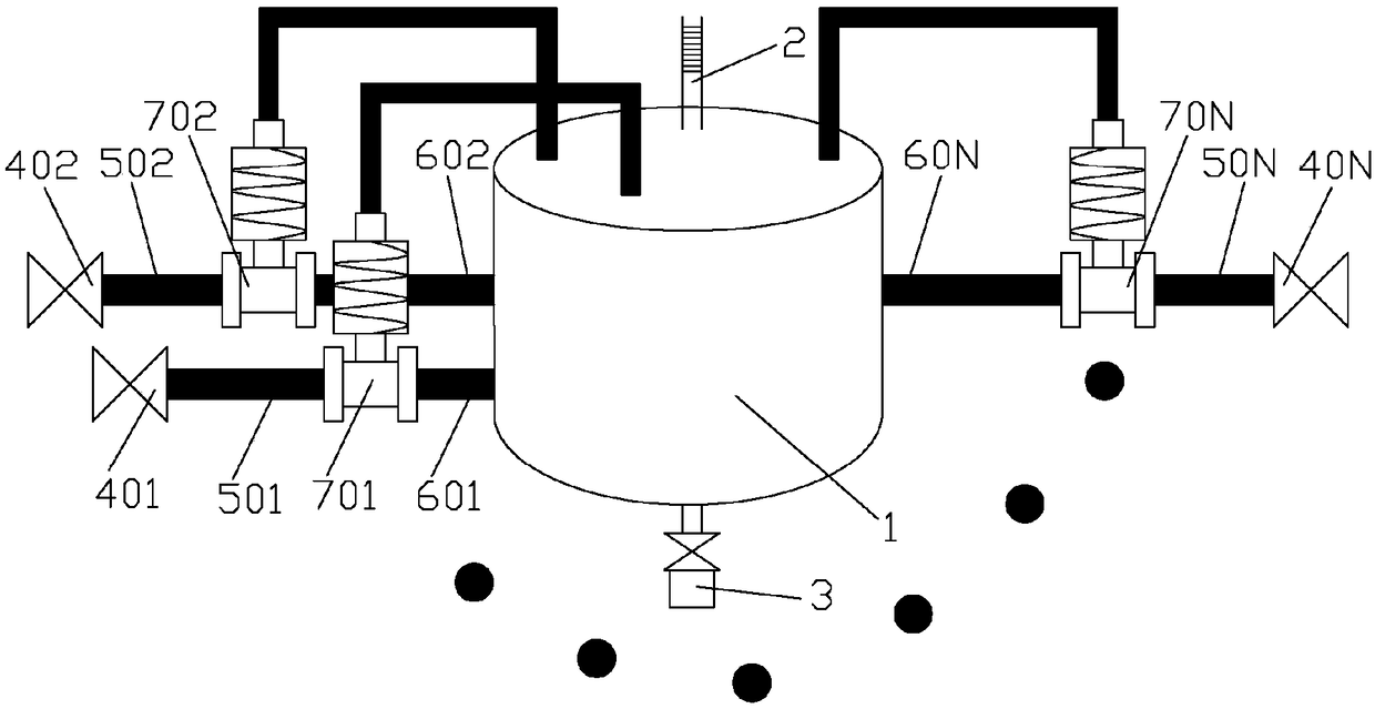
The invention discloses a self-operated temperature control valve detection device and detection method. The self-operated temperature control valve detection device comprises a test barrel, a steam branch which is arranged on the external side of the test barrel and connected with the test barrel, a thermometer which is arranged above the test barrel with the measuring end inserted into the testbarrel, and a blow-down valve which is installed on the bottom part of the test barrel. The steam branch comprises a steam piping valve, a first steam pipeline and a second steam pipeline. The steam piping valve is arranged on the steam inlet end of the first steam pipeline. The steam outlet end of the second steam pipeline is connected with the test barrel. The detected self-operated temperaturecontrol valve is connected between the steam outlet end of the first steam pipeline and the steam inlet end of the second steam pipeline, and the temperature sensor of the self-operated temperature control valve is arranged in the test barrel. According to the self-operated temperature control valve detection device and detection method, whole course control before and after use of the self-operated temperature control valve can be realized, and fault elimination and sensitivity test of multiple self-operated temperature control valves can be simultaneously performed.

Description

technical field [0001] The invention relates to the technical field of gas, in particular to a self-operated temperature control valve detection device and detection method. Background technique [0002] The gas contains moisture, which is gaseous when the temperature is high. When the temperature is low, the moisture in the gas will condense and drain out. At this time, the condensed water in the gas needs to be discharged, and the gas drainer can timely and effectively collect the condensed water in the pipeline. condensed water, and seal the gas pipeline to prevent gas leakage. The heat tracing device of the gas drainer is the supporting facility of the drainer, which ensures the normal operation of the gas drainer in the low temperature environment. Since the gas drain is often installed outdoors along with the pipeline, it is easily affected by temperature. In winter, when the temperature is too low, the inside of the drain often freezes, causing the drain to lose its ...

Claims


Application Information

Patent Timeline
IPC IPC(8): G01M13/00
CPCG01M13/00
Inventor 孙建胜宋照川穆建国李平均王馨薇李红兵尹鲁阳陈建刚
Owner SHANDONG IRON & STEEL CO LTD
Learn More