Tower clock control system and tower clock power down time chasing method

A technology for control systems and tower clocks, applied in general control systems, control/regulation systems, radio-controlled timers, etc., can solve problems such as low accuracy and large system volume, achieve complete functions, improve control accuracy, cost reduction effect

Inactive Publication Date: 2018-07-24
SHANDONG UNIV
View PDF4 Cites 1 Cited by
  • Summary
  • Abstract
  • Description
  • Claims
  • Application Information

AI Technical Summary

Problems solved by technology

With the development of the economy, there are more and more tower clocks in urban buildings. However, most of the existing tower clocks use small-scale integrated circuits to control stepping motors for time tracking. The entire system is bulky and the accuracy is not high.

Method used


Image

  • Tower clock control system and tower clock power down time chasing method
  • Tower clock control system and tower clock power down time chasing method
  • Tower clock control system and tower clock power down time chasing method

Examples


Embodiment 1

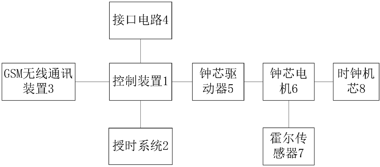
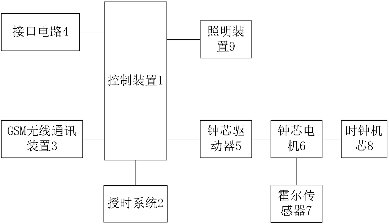
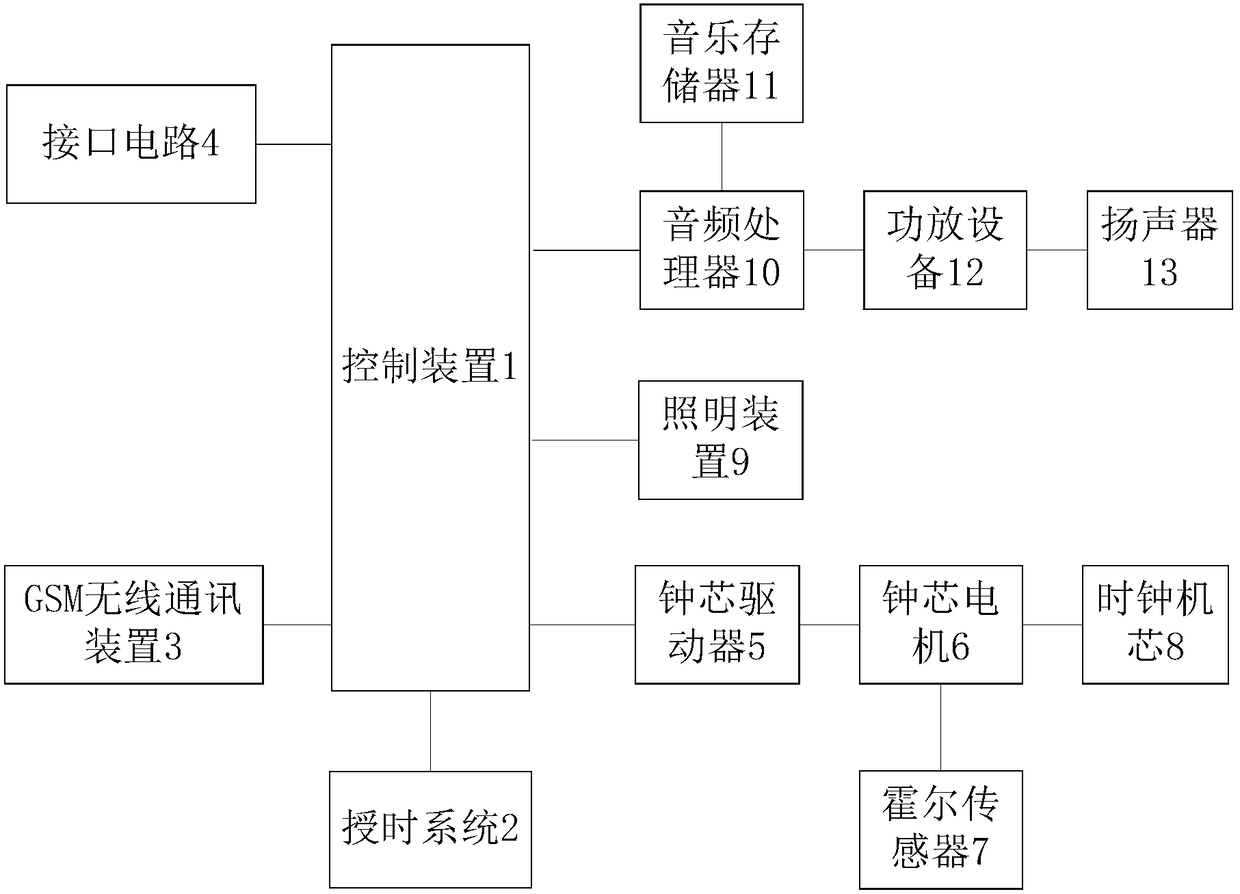
[0044] In this embodiment, the meanings of the reference signs are: 1. control device; 2. timing system; 3. GSM wireless communication device; 4. interface circuit; 5. clock core driver; 6. clock core motor; 8. Clock movement; 9. Lighting device; 10. Audio processor; 11. Music memory; 12. Power amplifier equipment; 13. Speaker.

[0045] to combine figure 1 , the tower clock control system provided by this embodiment includes:

[0046] Control device 1, timing system 2, clock core driver 5, clock core motor 6, Hall sensor 7, clock core 8, GSM wireless communication device 3, interface circuit 4;

[0047] The control device 1 is respectively connected to the timing system 2, the clock core driver 5, the GSM wireless communication device 3 and the interface circuit 4;

[0048] The clock core motor 6 is connected to the clock core driver 5 , the Hall sensor 7 and the clock core 8 respectively.

[0049] The tower clock control system provided by the embodiment of the present inv...

Embodiment 2

[0102] combine Figure 6 , the tower clock power-down tracking method provided in the embodiment of the present invention is applied to the tower clock control system provided in Embodiment 1, including:

[0103] Step S1, when it is detected that the system is powered on, obtain the latest power-down time information of the tower clock from the RTC chip, and obtain the power-down time record information from the clock core driver;

[0104] Step S2, according to the power-off time information and the record information of the power-off time adjustment, determine the type of time tracking;

[0105] Step S3, according to the type of time tracing, determine a suitable time tracing scheme to perform time tracing.

[0106] The tower clock power-down time tracking method provided by the embodiment of the present invention uses at least two of the timing methods of GPS time service, RTC chip time service, control device built-in clock time service, external key input time service, an...


PUM


Abstract

The invention provides a tower clock control system and a tower clock power down time chasing method. The system comprises a control device, a timing system, a clock core driver, a clock core motor, aHall sensor, a clock movement, a GSM wireless communication device and an interface circuit. The control device is connected with the timing system, the clock core driver, the GSM wireless communication device and the interface circuit. The clock core motor is connected with the clock core driver, the Hall sensor and the clock movement. According to the tower clock control system and the tower clock power down time chasing method, which are provided by the invention, at least two timing methods in GPS timing, RTC chip timing, clock timing of the control device, input timing based on an external key, and GSM-based input timing are used to carry out timing on a tower clock, so as to improve the accuracy of timing; according to the specific circumstances of power down, the type of time chasing is determined; a time chasing scheme is determined according to the type of time chasing; and when a specific time chasing process is carried out according to the time chasing scheme, the Hall sensor is used to judge the position of a pointer to realize accurate time chasing.

Description

technical field [0001] The invention relates to the field of large-scale clock control, in particular to a tower clock control system and a power-off time tracking method for the tower clock. Background technique [0002] Tower clock is an important role in public life, as a public facility in public places (such as stations, squares, airports, etc.), it provides convenience for people's lives. With the development of the economy, there are more and more tower clocks in urban buildings. However, most of the existing tower clocks use small-scale integrated circuits to control stepper motors for time tracking. The entire system is bulky and the accuracy is not high. Contents of the invention [0003] The technical problem to be solved by the present invention is to provide a tower clock control system and a power-down time tracking method for the tower clock, which adopts GPS timing, RTC chip timing, control device own clock timing, external button input timing, and GSM inpu...

Claims


Application Information

Patent Timeline
Patent Type & Authority Applications(China)
IPC IPC(8): G05B19/042G04R20/02
CPCG04R20/02G05B19/0428G05B2219/24215
Inventor 王小利袁胜忠周岩许光远吴子栋郑刘康
Owner SHANDONG UNIV
Why Eureka
Try Eureka