
Pulse signal amplifying circuit, echo signal receiving system and laser radar

A technology for amplifying circuits and pulse signals, which is applied in the field of electronic circuit design, can solve problems affecting pulse timing and measurement blind areas, and achieve the effects of reducing the maximum pulse width, improving timing accuracy, and avoiding output waveform broadening

Active Publication Date: 2022-03-01
TANWAY TECH (BEIJING) CO LTD
View PDF5 Cites 1 Cited by
  • Summary
  • Abstract
  • Description
  • Claims
  • Application Information

AI Technical Summary

Problems solved by technology

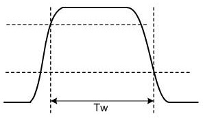
Among them, in the laser radar that uses the integral photodetector device as the photoelectric conversion device at the receiving end, when the optical pulse signal of the echo pulse is strong, the falling edge of the waveform corresponding to the electrical signal moves backward, and the waveform widens, thereby affecting the pulse timing. , resulting in a measurement blind zone

Method used


Image

  • Pulse signal amplifying circuit, echo signal receiving system and laser radar
  • Pulse signal amplifying circuit, echo signal receiving system and laser radar
  • Pulse signal amplifying circuit, echo signal receiving system and laser radar

Examples


Embodiment Construction

[0038] In order to more clearly understand the above objects, features and advantages of the present disclosure, the solutions of the present disclosure will be further described below. It should be noted that, in the case of no conflict, the embodiments of the present disclosure and the features in the embodiments can be combined with each other.

[0039] In the following description, many specific details are set forth in order to fully understand the present disclosure, but the present disclosure can also be implemented in other ways than described here; obviously, the embodiments in the description are only some of the embodiments of the present disclosure, and Not all examples.

[0040] The pulse signal amplifying circuit provided by the embodiment of the present disclosure is a photocurrent amplifying circuit with a pulse width limiting function, which is mainly used in the receiving end of the pulsed time-of-flight laser radar, and realizes the limitation of the pulse w...


PUM


Abstract

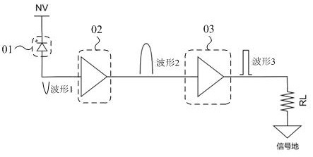
The invention relates to a pulse signal amplification circuit, an echo signal receiving system and a laser radar. The amplification circuit comprises a photoelectric conversion module, an amplifier module, a feedback module and a current compensation module. Bias voltage is connected to the positive input end of the amplifier module; the photoelectric conversion module is connected to the negative input end of the amplifier module through an electric connecting wire, the feedback module is connected between the electric connecting wire and the output end of the amplifier module, and the current compensation module is connected to the electric connecting wire; the photoelectric conversion module converts the optical pulse signal into a current pulse signal; the amplifier module converts the current pulse signal into a voltage pulse signal and amplifies the voltage pulse signal; the feedback module controls the gain of conversion from the current pulse signal to the voltage pulse signal; the current compensation module is switched on when the instantaneous light current in the current pulse signal exceeds the saturation threshold value of the amplifier module, and current compensation is carried out by using the input compensation current, so that the voltage of the negative input end is prevented from being lowered, the pulse width is prevented from being broadened, the pulse width is limited, and the blind area is improved.

Description

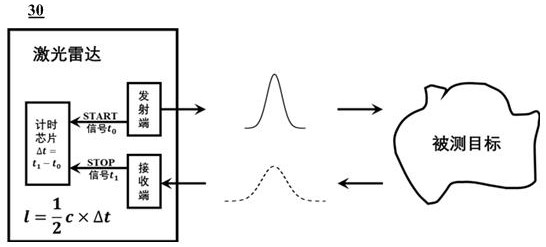
technical field [0001] The present disclosure relates to the technical field of electronic circuit design, in particular to a pulse signal amplifying circuit, an echo signal receiving system and a laser radar. Background technique [0002] Lidar is an active sensor that uses laser signals of specific wavelengths (such as ranging light pulses) to scan the surface of an object to obtain relevant characteristic information on the surface of the object. Compared with ordinary microwave radar, lidar has the advantages of high resolution, good concealment, strong anti-interference ability, small size and light weight. [0003] At present, most lidars use pulsed lasers as the time-of-flight (TOF) ranging scheme at the transmitter; correspondingly, the receiver timing based on the received echo pulses to achieve ranging. Among them, in the laser radar that uses the integral photodetector device as the photoelectric conversion device at the receiving end, when the optical pulse sign...

Claims


Application Information

Patent Timeline
Patent Type & Authority Applications(China)
IPC IPC(8): G01S7/487
CPCG01S7/487
Inventor 李洪鹏王百戈郑睿童沈罗丰占顺宇
Owner TANWAY TECH (BEIJING) CO LTD
Learn More