Ku-frequency-band miniaturized polarization rotating mechanism assembly

A technology of polarization rotation and frequency band, applied in the field of vehicle antenna, airborne antenna, and shipborne antenna, it can solve the problems of complex winding of power supply and signal cable of low noise amplifier, complex structure of feed network, and poor performance reliability. , to achieve the effects of stable electrical performance reliability, high gain, and low cross-polarization

Pending Publication Date: 2018-07-24
NO 54 INST OF CHINA ELECTRONICS SCI & TECH GRP
View PDF0 Cites 2 Cited by
  • Summary
  • Abstract
  • Description
  • Claims
  • Application Information

AI Technical Summary

Problems solved by technology

However, these two methods of adjusting the polarization angle also have their own disadvantages. The first disadvantage is that the installed feed network structure is complex and large because the entire feed network rotates together, which requires a larger servo motor to drive. The second disadvantage is that due to The low-noise amplifier in the receiving frequency band is connected with the feed network for rotation. The power supply and signal cable winding of the low-noise amplifier is more complicated, and it needs to occupy a certain amount of winding space. The third disadvantage is that the power supply and signal cables of the low-noise amplifier are often Winding, its performance reliability becomes worse

Method used


Image

  • Ku-frequency-band miniaturized polarization rotating mechanism assembly
  • Ku-frequency-band miniaturized polarization rotating mechanism assembly
  • Ku-frequency-band miniaturized polarization rotating mechanism assembly

Examples


Embodiment 1

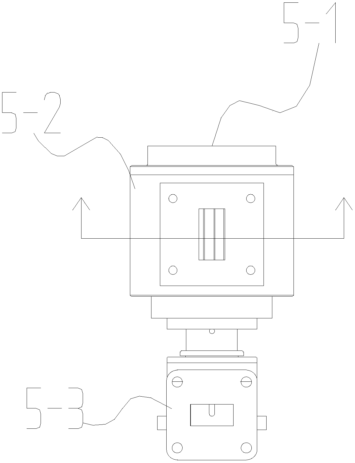
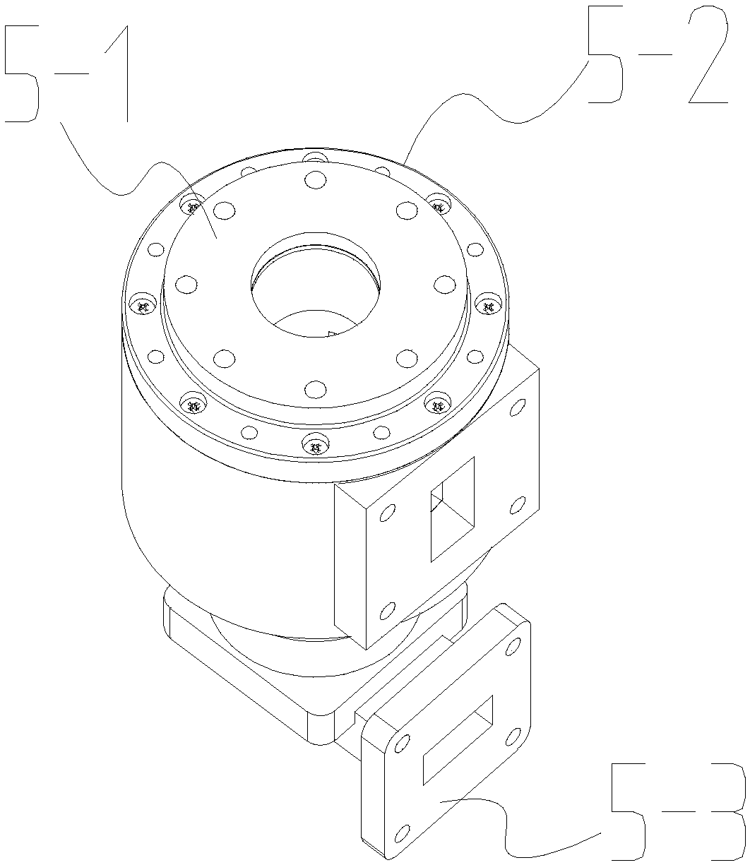
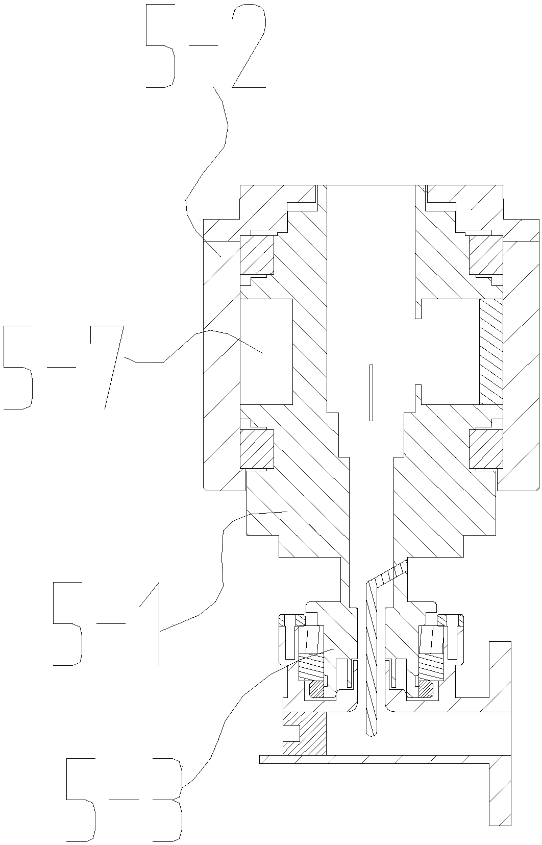
[0026] Example 1, such as Figure 1-4 As shown, a Ku-band miniaturized polarization rotating mechanism assembly is provided, which includes a rotating mechanism for adjusting signal polarization matching and a rotating joint 5-3 for transmitting signals. The rotating mechanism includes a center as a rotor. The waveguide 5-1 and the fixed cylinder 5-2 as the stator, the central waveguide is movably fitted in the inner cavity of the fixed cylinder;

[0027] The outer wall of the central waveguide is provided with a waveguide slot body, one end of the waveguide slot body is provided with a rotor matching block, and the stator matching block is located at the other end of the waveguide slot body. The fixed cylinder is wrapped around the central waveguide to close the top surface of the waveguide slot body. The rotor matching block is fixedly connected to the side wall of the central waveguide, the stator matching block is fixed to the inner wall of the fixed cylinder, and the rotor m...


PUM


Abstract

The invention discloses a Ku-frequency-band miniaturized polarization rotating mechanism assembly, and belongs to the field of communications. The Ku-frequency-band miniaturized polarization rotatingmechanism assembly comprises a rotating mechanism for adjusting signal polarization matching and a rotating joint for transmitting a signal, wherein the rotating mechanism comprises a center waveguideused as a rotor and a fixed barrel used as a stator; the center waveguide is movably assembled in an inner cavity of the fixed barrel; the side wall of the center waveguide is fixedly connected witha rotor matching block; the inner wall of the fixed barrel is fixedly connected with a stator matching block; a side waveguide channel which circularly extends along the periphery of the center waveguide is closed between the rotor matching block and the stator matching block; two ends of the side waveguide channel are respectively communicated with a signal input coupling port reserved on the center waveguide and a signal transceiver side port reserved on the fixed barrel; and a polarization angle of the side waveguide channel is changed by changing an angle between the rotor matching block and the stator matching block. A mode adopted in the Ku-frequency-band miniaturized polarization rotating mechanism assembly is to rotate a polarization separator inside a feed source network to realize matching of polarization of an antenna with polarization of an external signal; and as the rotated polarization separator is small in size, the complexity of the rotating mechanism is reduced, and the size of a servo motor which drives the rotation is reduced.

Description

Technical field [0001] The invention relates to a Ku-band miniaturized polarization rotating mechanism assembly in the fields of satellite communications, satellite broadcasting, and electronic reconnaissance signals, and is particularly suitable for miniaturization of structural size, high reliability of electrical performance, and multi-frequency sharing. The antenna is especially suitable for use in vehicle antennas, ship antennas, and airborne antennas. Background technique [0002] With the rapid development of modern communication technology, the demand for miniaturization of satellite communication systems is becoming stronger and stronger, which leads to more miniaturization requirements for the size of the antenna structure, in order to ensure that the antenna can be installed on the miniaturized carrier Inevitably, the antenna system is required to be small in size and light in weight, and the antenna is also required to have good electrical characteristics. Therefore,...

Claims


Application Information

Patent Timeline
Patent Type & Authority Applications(China)
IPC IPC(8): H01Q15/24
CPCH01Q15/24
Inventor 邓智勇张文静李振生伍捍东阮云国王垒张志彪刘迎喜李科娟李毅伟李盾张根会
Owner NO 54 INST OF CHINA ELECTRONICS SCI & TECH GRP
Why Eureka
Try Eureka