Efficiency optimization control method for switched reluctance motor system

A switched reluctance motor and optimized control technology, which is applied to control the direction of the generator through the change of the magnetic field, can solve the problems of differences, inability to obtain high control accuracy, and complex operating conditions of the motor, and achieve good results and good engineering application value , the effect of wide practicability

Active Publication Date: 2018-07-24
陈昊
View PDF2 Cites 6 Cited by
  • Summary
  • Abstract
  • Description
  • Claims
  • Application Information

AI Technical Summary

Problems solved by technology

Due to the differences between the simulation model of the switched reluctance motor and the actual system and the motor operating conditions are complex, it is difficult to accurately achieve the optimal efficiency by using the open-loop control of the look-up table, while the introduction of power closed-loop control and excitation parameter fitting methods is appropriate. It reduces the complexity of the lookup table and improves the calculation speed. On the other hand, it improves the control accuracy of the system and ensures that the output power changes with the change of the target power. However, the control method that relies on offline data often cannot achieve higher control. At the same time, through the analysis of a large number of simulation data and experimental data, it is concluded that the optimal efficiency cut-off angle of different loads and different speeds does not change significantly, and the optimal efficiency cut-off angle determined by simulation data and experimental data is different. Therefore, the existing efficiency optimization control methods for switched reluctance motors still have deficiencies.

Method used


Image

  • Efficiency optimization control method for switched reluctance motor system
  • Efficiency optimization control method for switched reluctance motor system
  • Efficiency optimization control method for switched reluctance motor system

Examples


Embodiment Construction

[0013] Below in conjunction with accompanying drawing, the example of the present invention will be further described:

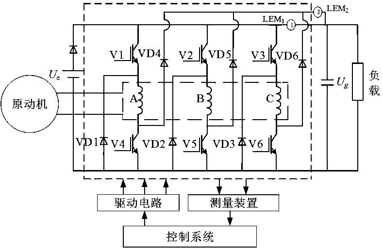
[0014] The switched reluctance motor system is mainly composed of five parts: prime mover, switched reluctance motor, power converter (including excitation power supply), control system and load, such as figure 1 shown. In this system, the switched reluctance motor, as the core component of electromechanical energy conversion, converts the input mechanical energy into electrical energy under the drag of the prime mover. The power converter is used as a channel for energy conversion. In the excitation phase, the external DC power supplies power to the phase winding through the power converter; in the freewheeling phase, the phase winding feeds back energy through the power converter. As the central part, the control system samples the given quantity (given power, given excitation voltage, etc.) and physical quantity (rotor position signal, phase voltage, pha...


PUM


Abstract

The invention discloses an efficiency optimization control method for a switched reluctance motor system. According to the method, a turn-on angle search interval is calculated according to generatedpower and a rotational speed; a turn-on angle is iteratively controlled within the search interval through adopting a golden section method, so that the efficiency of the system can be optimal, at thesame time, power closed-loop control is performed, and a turn-off angle and a current reference value are adjusted under a high-speed condition and a middle- and low-speed condition separately, so that output power changes according to the change of target power, finally the output power and the target power achieve dynamic balance, and the system outputs the target power with optimal efficiency.The method does not depend on motor model parameters, and has high control precision; and the method can automatically adjust the turn-on angle search interval, has high response speed, and has a high engineering application value.

Description

technical field [0001] The invention belongs to the field of switched reluctance motors and relates to a system efficiency optimization control method of switched reluctance motors. Background technique [0002] The switched reluctance motor has been successfully used in many occasions due to its simple structure, low manufacturing cost, strong fault tolerance, high operating reliability, and high efficiency in a wide speed range. The excitation control parameters of switched reluctance motors are turn-on angle, turn-off angle and current reference. When the switched reluctance motor runs at medium and low speeds, since the counter electromotive force is smaller than the DC bus voltage, the phase current amplitude can be limited within a certain range by current chopping control or voltage PWM control. When the switched reluctance motor runs at high speed, the counter electromotive force is greater than the DC bus voltage. After the main switching device of the power conver...

Claims


Application Information

Patent Timeline
Patent Type & Authority Applications(China)
IPC IPC(8): H02P9/30
CPCH02P9/30
Inventor 陈昊王星
Owner 陈昊
Why Eureka
Try Eureka