Cloud platform and its control method, unmanned aerial vehicle

A cloud platform and controller technology, applied in the field of cloud platform, can solve the problems that the camera cannot continue to shoot, the cloud platform swings randomly, etc.

Active Publication Date: 2021-10-22
SZ DJI TECH CO LTD
View PDF10 Cites 0 Cited by
  • Summary
  • Abstract
  • Description
  • Claims
  • Application Information

AI Technical Summary

Problems solved by technology

If there is no software limit, let the load rotate more than 30° in the roll direction, and reach more than 45°, the gimbal will swing randomly, making the camera mounted on the gimbal unable to continue shooting

Method used


Image

  • Cloud platform and its control method, unmanned aerial vehicle
  • Cloud platform and its control method, unmanned aerial vehicle
  • Cloud platform and its control method, unmanned aerial vehicle

Examples


Embodiment 1

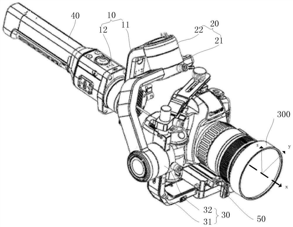
[0022] see figure 1 , Embodiment 1 of the present invention provides a pan / tilt 200 . The pan / tilt 200 of this embodiment is used to carry a load 300. In this embodiment, the load 300 is a camera, such as a camera, a camcorder, an infrared camera, an ultraviolet camera or similar devices. Certainly, in other embodiments, the load 300 may also be an image capture device such as an image sensor. see also figure 1 The gimbal 200 of this embodiment can control the payload 300 to rotate around the x-axis (ie, the roll direction), the y-axis (ie, the pitch direction) and the z-axis (ie, the yaw direction). Wherein, the x-axis, y-axis and z-axis form a three-dimensional Cartesian coordinate system. The rotation of the payload 300 around the y-axis corresponds to the attitude change of the payload 300 in the pitch direction, the rotation of the payload 300 around the z-axis corresponds to the attitude change of the payload 300 in the yaw direction, and the rotation of the payload 3...

Embodiment 2

[0044] see Figure 5 , Embodiment 2 of the present invention provides an unmanned aerial vehicle, and the unmanned aerial vehicle may include a fuselage 100, a gimbal 200, and a load 300 mounted on the gimbal 200, wherein the gimbal 200 is the above-mentioned embodiment For the pan / tilt 200 of Example 1, the structure, function, working principle and effect of the pan / tilt 200 can be referred to the description of Embodiment 1, and will not be repeated here.

[0045] In this embodiment, the first motor 12 of the pan / tilt 200 is fixed on the fuselage 100 . Optionally, the first motor 12 is fixed on the bottom of the fuselage 100 through a base.

[0046] The UAV in this embodiment can be a multi-rotor UAV or a non-rotor UAV.

Embodiment 3

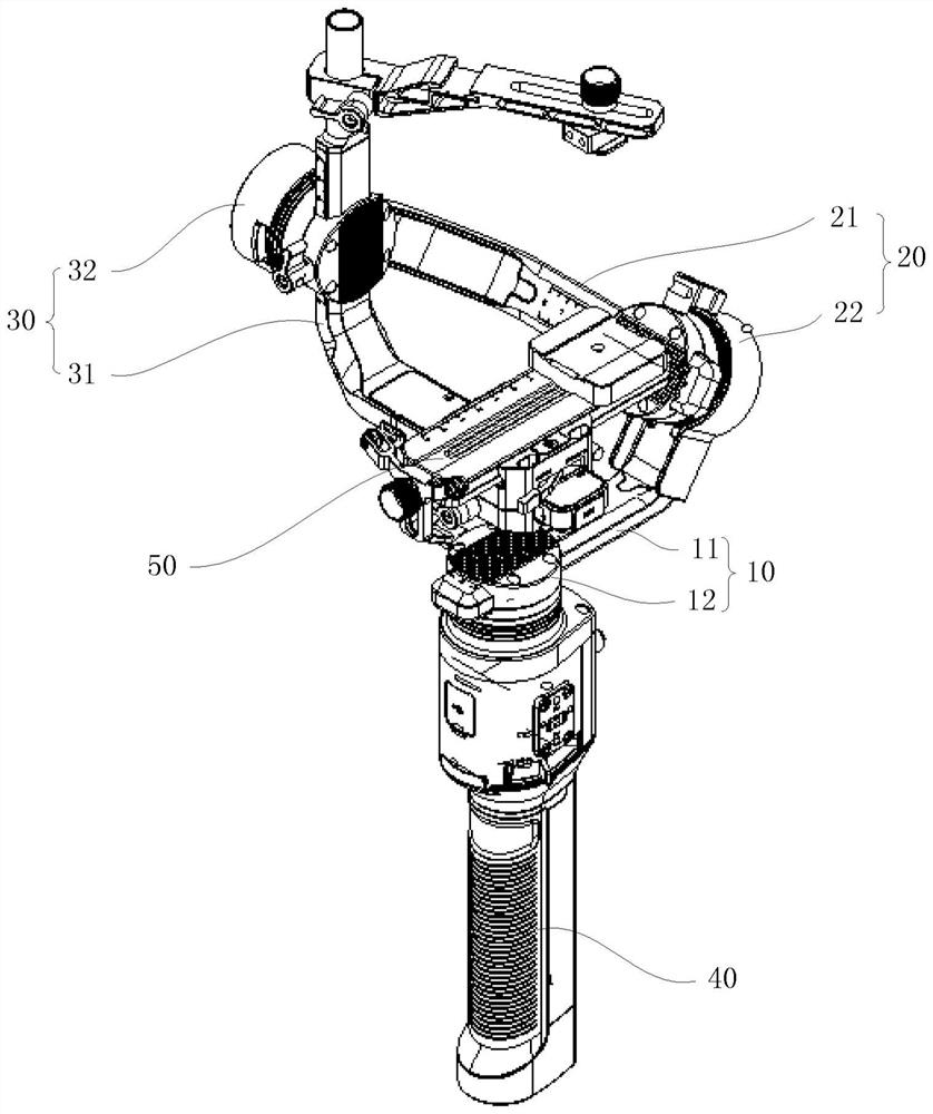
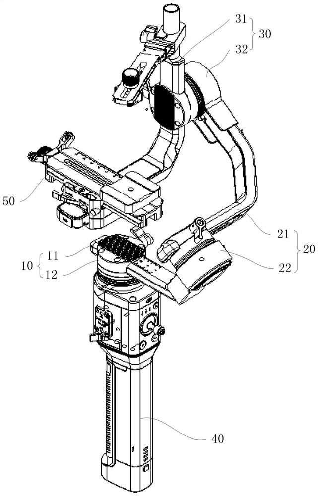
[0048] see Figure 6 , Embodiment 3 of the present invention provides a pan-tilt control method. Wherein, the pan / tilt 200 includes a first shaft assembly 10 , a second shaft assembly 20 , a third shaft assembly 30 and a handle bar 40 . The first shaft assembly 10 includes a first shaft arm 11 and a first motor 12 mounted on one end of the first shaft arm 11, and the second shaft assembly 20 includes a second shaft arm 21 and a first motor 12 mounted on the second shaft arm 11. The second motor 22 at one end of the shaft arm 21, the third shaft assembly 30 includes a third shaft arm 31 and a third motor 32 mounted on one end of the third shaft arm 31, the first shaft arm 11 is far away from the One end of the first motor 12 is fixedly connected to the second motor 22, and one end of the second shaft arm 21 away from the second motor 22 is fixedly connected to the third motor 32, and the third shaft arm 31 is used for carrying The load 300 ; wherein the third motor 32 is a pi...


PUM


Abstract

The invention provides a cloud platform and its control method, and an unmanned aerial vehicle, wherein the platform includes a first axis assembly, a second axis assembly and a third axis assembly, and the first axis assembly includes a first axis arm and is installed on the first axis The first motor at one end of the arm, the second shaft assembly includes a second shaft arm and a second motor installed at one end of the second shaft arm, and the third shaft assembly includes a third shaft arm and a third motor installed at one end of the third shaft arm , the end of the first shaft arm away from the first motor is fixedly connected to the second motor, the end of the second shaft arm away from the second motor is fixedly connected to the third motor, the third shaft arm is used to carry loads, and the first motor can be used as a roll axis The motor, the second motor can be used as one of the yaw axis motor and the pitch axis motor, and the third motor can be used as the other of the yaw axis motor and the pitch axis motor; the roll axis motor rotates to drive the load around x The axis rotates, and drives the yaw axis motor and the pitch axis motor to rotate synchronously around the rotation axis of the roll axis motor, so as to avoid the gimbal from spinning wildly.

Description

technical field [0001] The invention relates to the field of cloud platforms, in particular to a cloud platform, a control method thereof, and an unmanned aerial vehicle. Background technique [0002] At present, the gimbals on the market have software angle limits in the roll direction of the mounted load, generally about ±30°. If the software limit is not added, the rotation of the load in the roll direction exceeds 30°, reaching more than 45°, and the gimbal will swing randomly, making it impossible for the camera mounted on the gimbal to continue shooting. However, when shooting some scenes, the user would like to shoot at a large angle in the rolling direction, and also hope to shoot some special effects scenes that require the load to rotate at a large angle in the rolling direction, such as the picture of the sky spinning. Contents of the invention [0003] The invention provides a cloud platform, a control method thereof, and an unmanned aerial vehicle. [0004] ...

Claims


Application Information

Patent Timeline
Patent Type & Authority Patents(China)
IPC IPC(8): G05D3/12
CPCF16M11/121F16M11/18F16M13/04B64D47/08G03B17/563F16M13/02F16M13/00F16M11/2071F16M11/123F16M11/10F16M11/105F16M11/2064B64C39/024B64U2101/30F16M11/12F16M13/022G03B15/006G03B17/561G05B19/042G05B2219/2637B64U10/13
Inventor 苏铁潘立忠
Owner SZ DJI TECH CO LTD
Why Eureka
Try Eureka