Slurry mixer for battery electrode

A technology for battery electrodes and mixers, which is applied in the direction of mixer accessories, electrode manufacturing, and mixers with rotating stirring devices, etc. It can solve the problem of difficult to set the motor rotation speed at high speed, unable to greatly increase production, and unable to maintain the best state, etc. problem, achieve the effects of shortening the stirring time, simple structure, and preventing scalding

Active Publication Date: 2018-07-27
TSI CO LTD
View PDF7 Cites 3 Cited by
  • Summary
  • Abstract
  • Description
  • Claims
  • Application Information

AI Technical Summary

Problems solved by technology

[0010] However, the mixer impeller of the above-mentioned prior art forms a multi-layer structure, so not only the structure is complicated, but also a plurality of impellers are fixed and rotated together on a single drive shaft, so when the mixed material is stirred, the shaft used to rotate the drive shaft The rotation load of the motor plays a big role, where the impeller moves the mixed material up and down while dispersing and performing the work of uniform mixing
Therefore, it is difficult to set the rotation speed of the motor at a high speed, and there is a limitation in shortening the slurry stirring time, and there is a disadvantage that the output cannot be greatly increased
[0011] In addition, the disadvantages of the prior art are as follows: the structure and shape of the impeller are fixed, so the rotational load acting on the motor varies according to the particle size or specific gravity of the mixed material, and the rotational load acting on the motor varies depending on the mixing ratio of the mixed material. The rotating load of the motor, so it cannot be kept in optimum condition
Therefore, the higher the rotation load, the greater the load on the motor, which shortens the life and prolongs the stirring time. On the contrary, the lower the rotation load, the lower the stirring efficiency.

Method used


Image

  • Slurry mixer for battery electrode
  • Slurry mixer for battery electrode
  • Slurry mixer for battery electrode

Examples


Embodiment Construction

[0046] Hereinafter, preferred embodiments of the present invention will be described in detail with reference to the accompanying drawings.

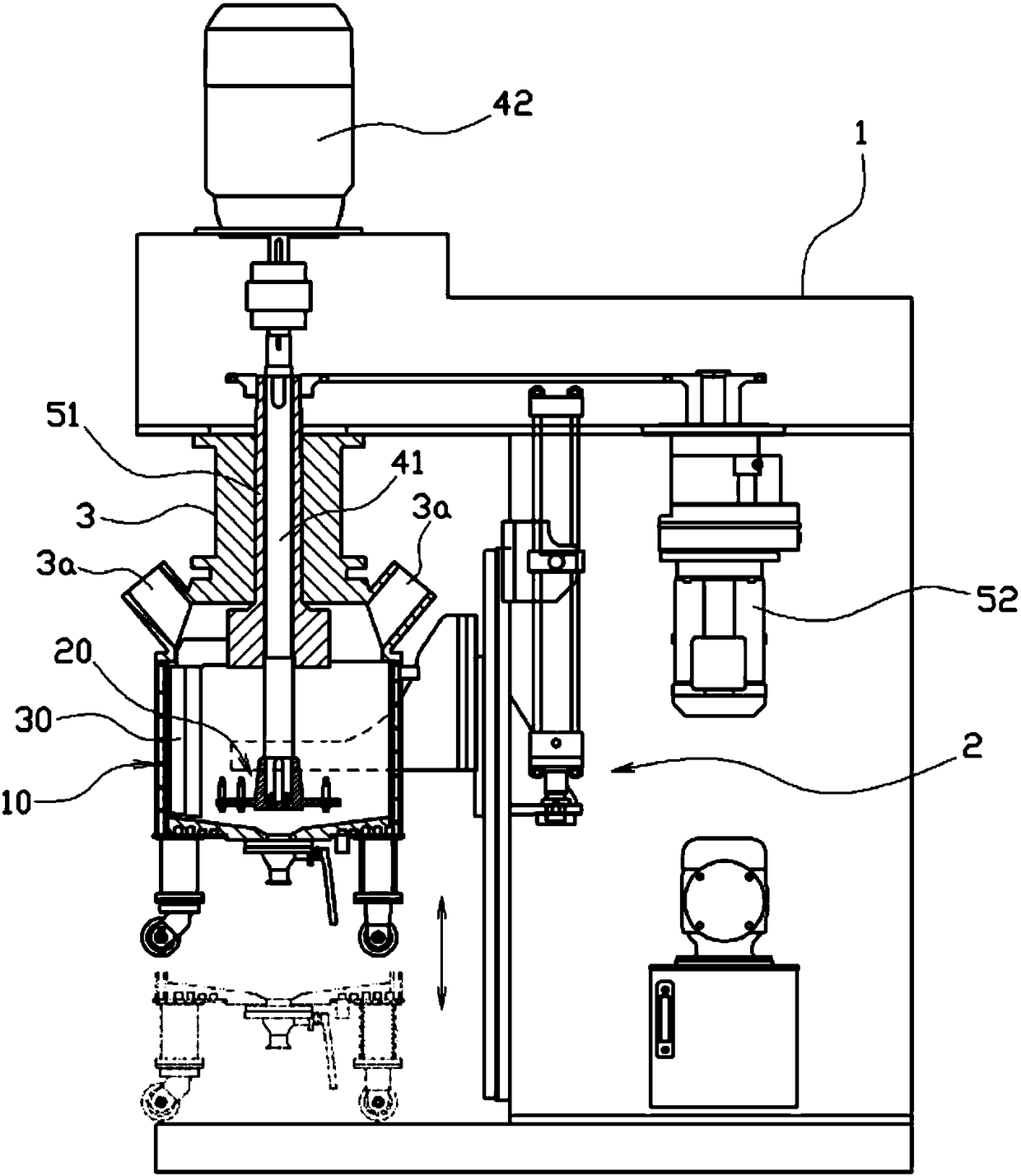
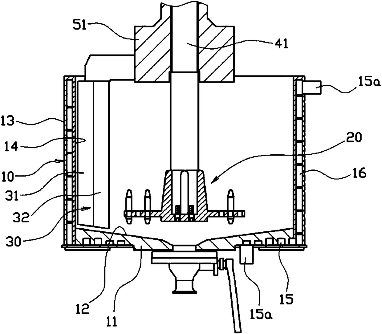
[0047] figure 1 by figure 2 It is a cross-sectional view showing a slurry mixer for battery electrodes according to the present invention. As shown in the figure, it has a container 10 that can accommodate the mixed material for manufacturing the slurry for battery electrodes. The bottom 11 of the container 10 is formed from the center toward The sloped bottom surface 12 whose outer side gradually becomes higher forms an inner peripheral surface 14 standing upright from the edge of the sloped bottom surface 12 on the side wall 13 of the container 10 .

[0048] The container 10 is arranged on the main body of the mixer 1, and can be moved up and down by the lifting tool 2 composed of a driving cylinder and a guide rail. The upper part can be opened and closed by the cover 3 provided on the main body 1 of the mixer. The inlet 3a inside...


PUM


Abstract

According to the present invention, provided is a slurry mixer for a battery electrode which allows an agitator to separately have a high-speed agitator and a low-speed agitator to input a mixed material at the same time so as to uniformly disperse and mix the same, and allows the configuration of the high-speed agitator to be maximally simplified to minimize a rotating load so as to be able to set a high-speed rotation of an electric motor, thereby improving the productivity by greatly shortening an agitation time of slurry. The slurry mixer for the battery electrode of the present inventioncomprises: a container for accommodating a mixed material consisting of a liquid material and a powdery material, and having a bottom portion formed with an inclined bottom surface and a side wall portion formed with an inner circumferential surface erected from an edge portion of the inclined bottom surface; a high-speed agitator for flowing and agitating the mixed material, and having an inclined cylindrical portion, a plurality of radially-arranged agitating pieces, a rotating plate having agitating grooves alternately arranged, and a plurality of agitating rods fixed to the agitating pieces of the rotating plate; a high-speed electric motor for rotating the high-speed agitator; a low-speed agitator having a blade surface for separating the mixed material attached onto the inner circumferential surface of the container therefrom and a swirling surface for moving the mixed material located at an edge portion in the container to the center; and a low-speed electric motor for rotatingthe low-speed agitator.

Description

technical field [0001] The present invention relates to a slurry mixer for battery electrodes, and more specifically relates to a slurry mixer for battery electrodes capable of dispersing and uniformly mixing materials when manufacturing slurry used to form battery electrodes. Background technique [0002] Recently, for batteries that can be used continuously by recharging, solutions to environmental pollution are being proposed to actively respond to the saving of fossil fuels and the reuse of renewable energy, and the power of portable electronic devices such as mobile phones and notebook computers is widely used. Secondary batteries, particularly for electric vehicles, are being actively developed, and thus the production volume of secondary batteries is being greatly increased. [0003] In the method of manufacturing the secondary battery, the electrode is formed by the coating method by applying an electrode slurry composed of an electrode active material, a conductive ...

Claims


Application Information

Patent Timeline
Patent Type & Authority Applications(China)
IPC IPC(8): B01F7/16B01F15/06
CPCB01F27/11B01F27/091B01F27/192B01F27/84B01F2035/98B01F35/92B01F2101/59Y02E60/10H01M4/04H01M4/0404Y02P70/50B01F23/53B01F27/90B01F35/3204
Inventor 表仁植
Owner TSI CO LTD
Why Eureka
Try Eureka