Eureka AIR delivers breakthrough ideas for toughest innovation challenges, trusted by R&D personnel around the world.

3D printing head, application method thereof and glue applied to 3D printing head

A print head and 3D technology, applied in the field of 3D printing, can solve the problems of unguaranteed firmness of layers, poor adhesion of printing materials with small cross-sections, difficult processing of parts, etc. Excellent, firmness-enhancing effect

Active Publication Date: 2018-07-27
NANTONG INST OF TECH
View PDF7 Cites 3 Cited by
  • Summary
  • Abstract
  • Description
  • Claims
  • Application Information

AI Technical Summary

Problems solved by technology

[0003] 3D printers are still in continuous research and development, and 3D printing technology is developing towards the diversification of printing materials and the quality optimization of printed products. Among them, the print head of the 3D printer in the prior art is usually a discharge hole, from which the nozzle is sprayed. The printed materials are then stacked layer by layer to form the desired product. However, in the prior art, the specifications of the 3D printing discharge holes are all fixed, and the cross-sectional size of the printed materials ejected is fixed. It is difficult to process and shape, and the material adhesion of small cross-section printing materials is poor, and the firmness between layers cannot be guaranteed

Method used


Image

  • 3D printing head, application method thereof and glue applied to 3D printing head
  • 3D printing head, application method thereof and glue applied to 3D printing head
  • 3D printing head, application method thereof and glue applied to 3D printing head

Examples


Embodiment 1

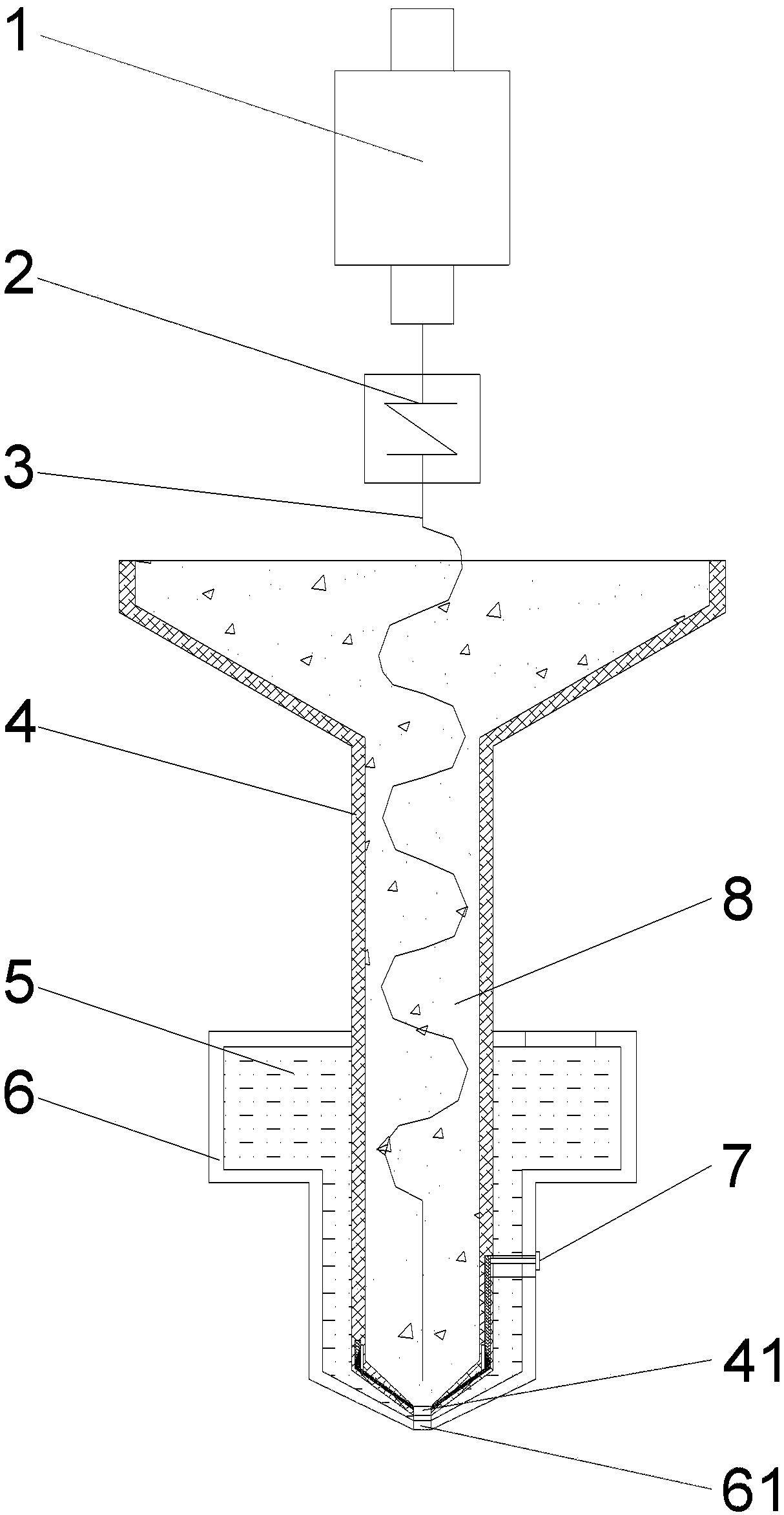
[0047] In an exemplary embodiment of the present application, a 3D printing head is provided. Such as figure 1 As shown, the present application includes a barrel 4, a bore telescoping device 7 and a glue discharge device.

[0048] Each component of this embodiment will be described in detail below.

[0049] The print head is a screw extrusion print head, the motor 1 drives the extrusion screw 3 through the coupling 2, the printing material is built in the barrel 4, the barrel 4 is vertically arranged, and the lower end of the barrel 4 is opened with a discharge hole 41, As the extrusion screw 3 rotates, the printing material is extruded from the discharge hole 41 .

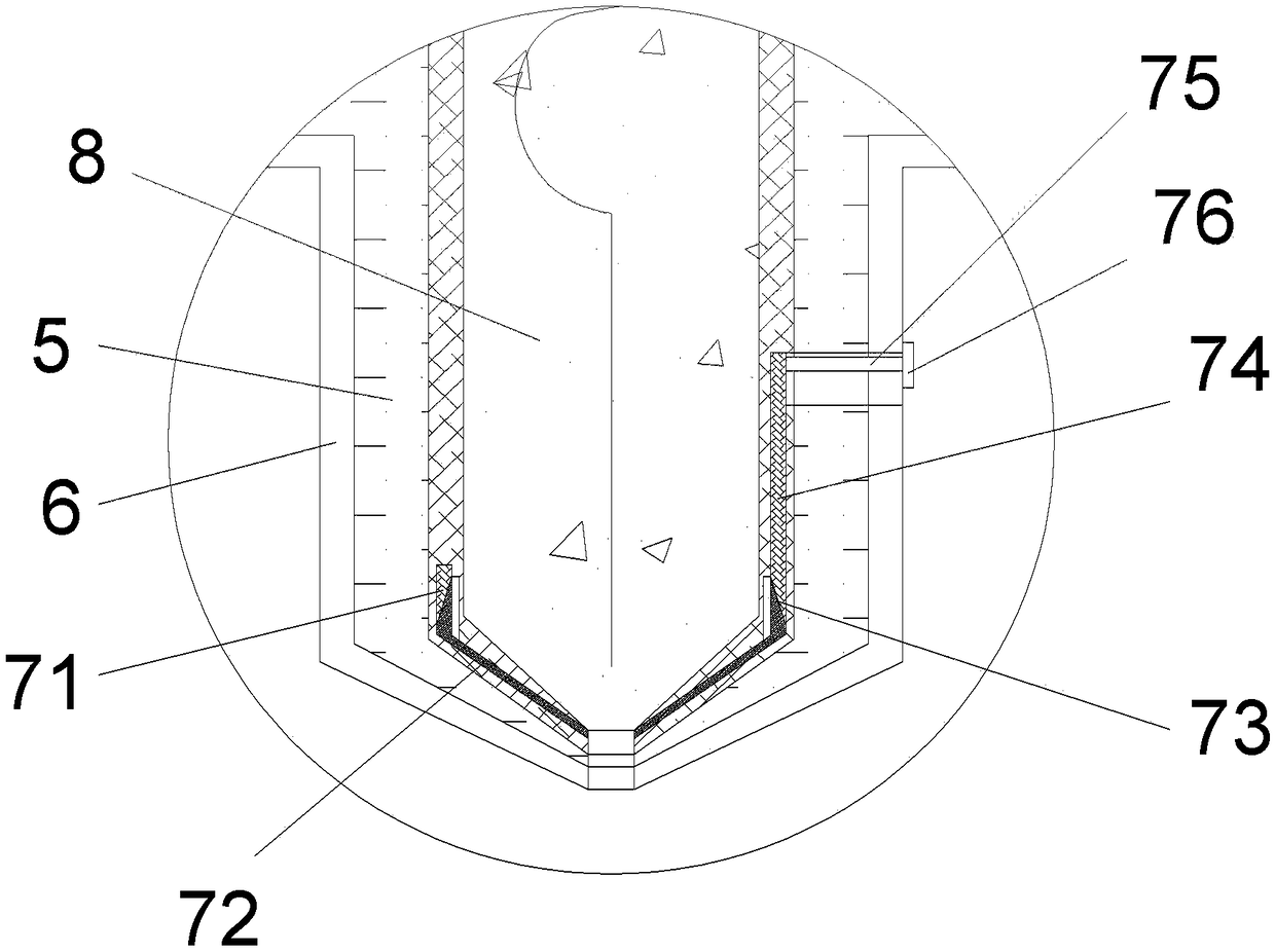
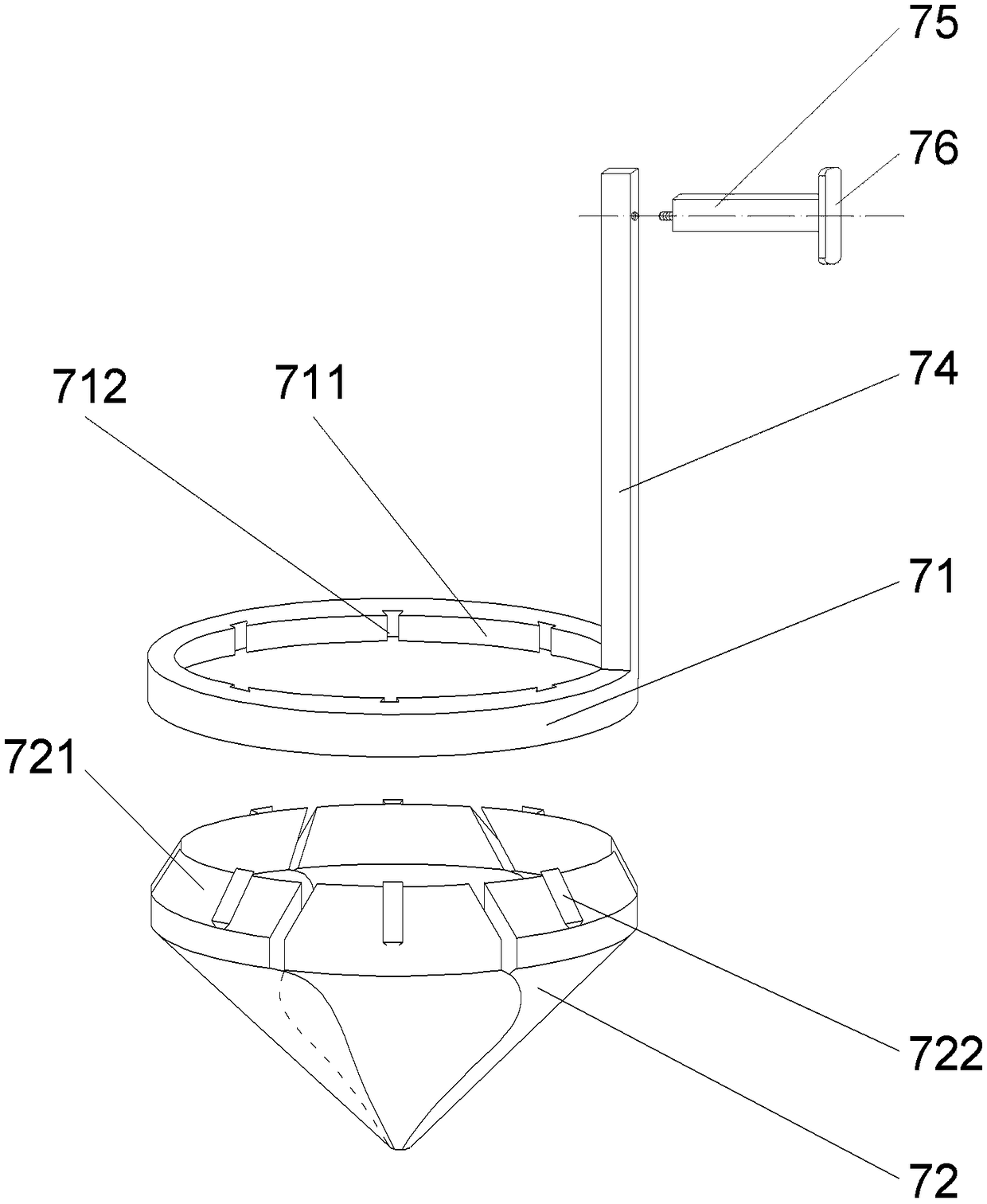
[0050] Such as figure 2 As shown, the glue discharge device includes a rubber cylinder 6 which is arranged around the cylinder, and an annular glue storage chamber is formed between the rubber cylinder 6 and the cylinder 4. Glue 5 is stored in the glue storage chamber, and the lower end of the glue cylinder 6...

Embodiment 2

[0055] The printing material is concrete, and the glue includes the following components in parts by weight: 8 parts of softening oil, 6 parts of asphalt, 10 parts of rubber, 2 parts of reinforced fiber, 3 parts of diatomaceous earth, and 1 part of stabilizer. Among them, the rubber includes styrene-butadiene thermoplastic rubber, the reinforcing fiber is glass fiber, the softening oil is a mixed oil of aromatic oil and castor oil in a ratio of 1:1, and the ratio of aromatic oil and castor oil is 1:1.5. The stabilizer is trioctyl phosphate.

Embodiment 3

[0057] In the case that other technical means are the same as in Example 1, the glue includes the following components in parts by weight: 9 parts of softening oil, 7 parts of asphalt, 11 parts of rubber, 3 parts of reinforced fiber, 4 parts of diatomaceous earth, stabilizer 2 servings. The stabilizer is a mixture of trioctyl phosphate and polyvinylpyrrolidone in any ratio.


PUM

PropertyMeasurementUnit
diameteraaaaaaaaaa

Abstract

The invention provides a 3D printing head. The 3D printing head comprises a charging barrel, an aperture expansion device and a glue outlet device. The lower end of the charging barrel is provided with a discharge hole. The aperture expansion device is provided with a movable baffle. The glue outlet device is arranged on the periphery of the charging barrel in a surrounding mode. The lower end ofthe glue outlet device is provided with a glue outlet. The invention further provides an application method of the 3D printing head. The application method comprises the steps of applying force to theaperture expansion device to reform a new discharge hole; extruding out a printing material in the charging barrel from the new discharge hole to enable the peripheral surface of the printing material to be stained with the glue. The invention further provides the glue for the printing head. Concrete serves as the printing material. The glue comprises softening oil, asphalt, rubber, reinforced fiber, kieselguhr and a stabilizing agent. The 3D printing head has the advantages that the aperture expansion device is mounted on the 3D printing head; the discharge cross section of the discharge hole becomes smaller, and the material with the small cross section can be extruded; meanwhile, the glue outlet device is additionally arranged, the glue outlet is arranged outside the discharge hole, the surface of the printing material can be stained with the glue after the printing material is extruded out from the discharge hole, and the next step of bonding is facilitated.

Description

technical field [0001] The present application relates to the technical field of 3D printing, and in particular to a 3D printing head, its usage method and glue applied thereon. Background technique [0002] 3D printing technology is a method based on three-dimensional model data, which uses materials to be superimposed layer by layer to manufacture solid parts. This method subverts the traditional production idea, does not require mechanical processing or molds, does not depend on whether the traditional production process can be realized, and greatly shortens the product development cycle. This technology has been widely used in the fields of machinery, automobile, education, medical treatment, construction industry and national defense, and has achieved significant economic benefits. [0003] 3D printers are still in continuous research and development, and 3D printing technology is developing towards the diversification of printing materials and the quality optimization...

Claims


Application Information

Patent Timeline
Patent Type & Authority Applications(China)
IPC IPC(8): B28B1/00B33Y30/00B33Y10/00C08L9/06C08L95/00C08L91/00C08K13/04C08K7/14C08K3/34
CPCB28B1/001B33Y10/00B33Y30/00C08L9/06C08L2205/03C08L95/00C08L91/00C08K13/04C08K7/14C08K3/34
Inventor 黄天成李彬顾海张捷曹赛男姜杰孙健华
Owner NANTONG INST OF TECH
Why Eureka
Eureka Blog
Learn More