Turbine rotor welding joint detection system

A technology for steam turbine rotors and welded joints, applied in measuring devices, instruments, scientific instruments, etc., can solve the problems of stress distribution changes in welded joints, high welding performance requirements, high welding process and inspection and testing technology requirements, and achieve stable and efficient operation. Avoid the effect of axial play

Active Publication Date: 2018-07-27
SUZHOU NUCLEAR POWER RES INST +2
View PDF12 Cites 2 Cited by
  • Summary
  • Abstract
  • Description
  • Claims
  • Application Information

AI Technical Summary

Problems solved by technology

[0002] Welded rotors have many advantages such as compact structure, high strength, convenient processing, reasonable material utilization and good rotor rigidity. High requirements and weak performance areas of welded joints, etc.
[0005] However, during the operation stage of the steam turbine rotor, all the blades have been installed in place. Due to space constraints, it is difficult to directly inspect many parts of the welded joints of the rotor or manually place the probe at the

Method used


Image

  • Turbine rotor welding joint detection system
  • Turbine rotor welding joint detection system
  • Turbine rotor welding joint detection system

Examples


Example Embodiment

[0032] The present invention will be further described below with reference to the drawings and embodiments.

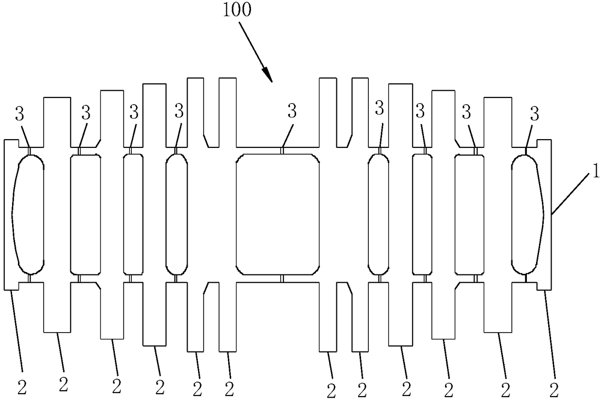
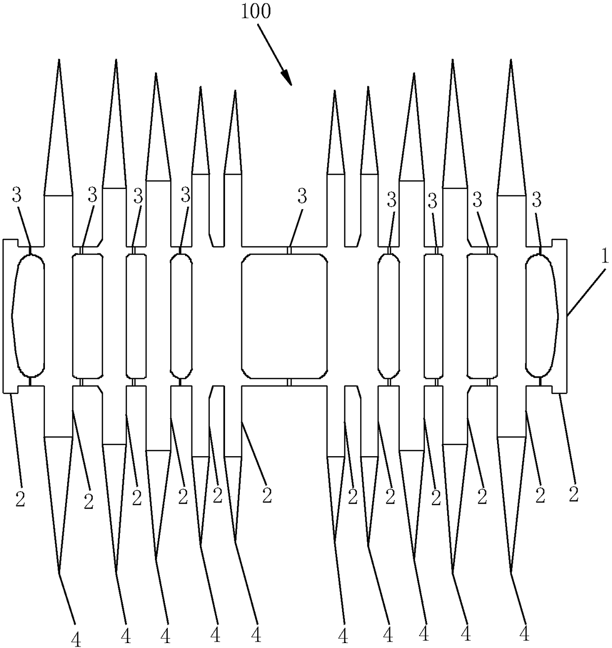
[0033] Such as Figure 1 to Figure 2 As shown, the steam turbine rotor 100 includes a main shaft 1 and a plurality of impellers 2 arranged on the circumference of the main shaft 1. All the impellers 2 are arranged at intervals along the axial direction of the main shaft 1, and the outermost circumference of each impeller 2 is provided along the main shaft. 1 of the annular blades 4 extending radially outward, the welding joints 3 of the rotor 100 are annular welds arranged on the main shaft 1 at intervals, and the welding joints 3 are located between adjacent impellers 2. The minimum distance between two adjacent impellers 2 is only 200 mm, and the circumference of the main shaft 11 is 4-5 m.

[0034] The welding joint 3 detection method includes: using video detection method to detect the surface defects of the welding joint 3; using the array eddy current detection metho...


PUM


Abstract

The invention relates to the technical field of detection equipment, and in particular, relates to a turbine rotor welding joint detection system at least including a scanning robot for clamping a detection probe to move along the surface of a welded joint. The scanning robot includes a machine base which can walk along the surface of the welding joint, a clamping assembly mounted in the middle ofthe machine base and used for clamping the detection probe, a first driving assembly mounted on the machine seat and used for driving the clamping assembly to adjust relative to the position of the machine seat, a driving wheel mounted at the bottom of the machine seat, a second driving assembly for driving the driving wheel to rotate, a controller in communication connection with the first driving assembly and the second driving assembly and for controlling the work states of the first driving assembly and the second driving assembly, and a power device for providing power for the first driving assembly, the second driving assembly and the controller. The detection system can conveniently detect the welding joint, so as to ensure stable and highly efficient operation of a turbine unit.

Description

technical field [0001] The invention relates to the technical field of detection equipment, in particular to a detection system for a welded joint of a steam turbine rotor. Background technique [0002] Welded rotors have many advantages such as compact structure, high strength, convenient processing, reasonable material utilization and good rotor rigidity. High requirements and weak performance areas of welded joints, etc. Due to the existence of the weak zone, it is very important to regularly check the quality and performance of the welded joints in order to ensure the safe operation of the rotor. [0003] As an important part of the power station, the safety and reliability of the steam turbine directly affects the safe and economical operation of the power station. With the development of steam turbine technology, the application of welded rotors of steam turbines is becoming more and more extensive. It is necessary to develop reliable solutions to ensure the safe, st...

Claims


Application Information

Patent Timeline
IPC IPC(8): G01N33/00
CPCG01N33/00
Inventor 徐宁童忠贵刘晓睿马龙夏樑刘立鹏
Owner SUZHOU NUCLEAR POWER RES INST
Why Eureka
Try Eureka