Bipolar plate sealing process for fuel cells

A fuel cell cathode and fuel cell technology, applied in the direction of battery electrodes, circuits, electrical components, etc., can solve the problems of UV curing difficulties, invisible adhesive joints, etc., to avoid blocking the cooling flow field, clean and beautiful appearance, and stack Fast and accurate temperature control

Inactive Publication Date: 2018-07-27
SHANGHAI SHENLI TECH CO LTD
View PDF7 Cites 6 Cited by
  • Summary
  • Abstract
  • Description
  • Claims
  • Application Information

AI Technical Summary

Problems solved by technology

For example, UV curing is more difficult because the bonded joint is not visible

Method used


Image

  • Bipolar plate sealing process for fuel cells
  • Bipolar plate sealing process for fuel cells

Examples


Embodiment 1

[0022] According to the shape of the bipolar plate, the gluing area of ​​the stencil is made. The gluing area on the stencil is indented by 1mm from the outer contour of the bipolar plate, and the other areas of the plate are glued as a whole. Use 150-mesh polyester mesh to make the mesh panel, and use oily photosensitive glue to seal the mesh. The prepared stencil is fixed on the screen printing equipment, and the method of screen printing is adopted. After the glue is applied, the cathode and anode plates are combined, placed in the limit tooling, and the limit tool is placed in a hot press for heat curing , the temperature of the hot press is 150 degrees, the pressure is 0.7 MPa, the curing time is 30 minutes, cooling, and the bipolar plate bonding is completed.

Embodiment 2

[0024] A fuel cell bipolar plate sealing process adopts the following steps:

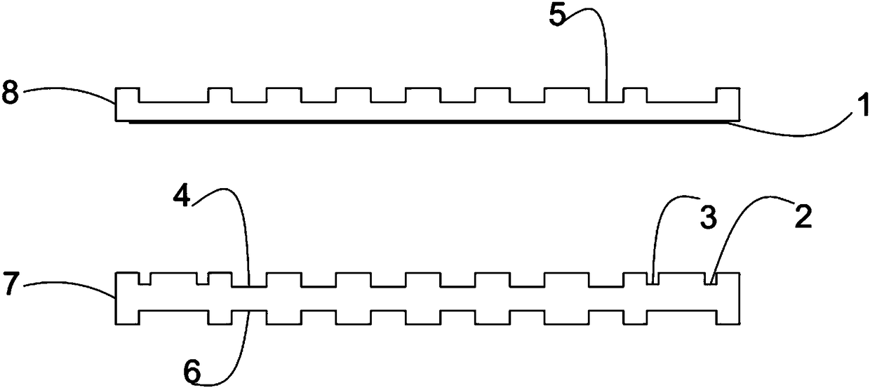
[0025] (1) Process a circle of the second glue overflow groove 3 and the first glue overflow groove 2 on the periphery and outer contour of the coolant flow field 4 on the fuel cell anode plate 7, and also have an oxidant flow field 6 on the anode plate 7 ;

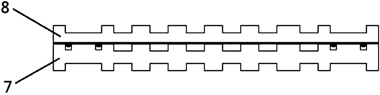
[0026] (2) Coating conductive glue 1 on the smooth surface of cathode plate 8, the other side is fuel flow field 5, as figure 1 As shown, the conductive adhesive is applied by screen printing equipment, and the printing screen used is a polyester screen with a mesh number of 120. The glue thickness is 0.01mm;

[0027] (3) Place the anode plate and the surface of the cathode plate coated with conductive adhesive together in the limit tooling, put the limit tool into a hot press for hot pressing and curing, and control the temperature for hot pressing and curing to 120°C. The pressure is 0.1Mpa, the time is 90min, and the sealed connection is ...

Embodiment 3

[0029] A fuel cell bipolar plate sealing process adopts the following steps:

[0030] (1) Process a circle of the second glue overflow groove 3 and the first glue overflow groove 2 on the periphery and outer contour of the coolant flow field 4 on the fuel cell anode plate 7, and also have an oxidant flow field 6 on the anode plate 7 ;

[0031] (2) Coating conductive glue 1 on the smooth surface of cathode plate 8, the other side is fuel flow field 5, as figure 1 As shown, the conductive adhesive is coated with screen printing equipment, and the printing screen used is a polyester screen with a mesh number of 200. Glue thickness is 0.05mm;

[0032] (3) Place the anode plate and the surface of the cathode plate coated with conductive adhesive together in the limit tooling, put the limit tool into a hot press for hot pressing and curing, and control the temperature for hot pressing and curing to 120°C. The pressure is 1Mpa, the time is 30min, and the sealed connection is compl...


PUM


Abstract

The invention relates to a bipolar plate sealing process for fuel cells. A loop of glue-spilling groove is processed on a fuel cell negative plate liquid coolant flow field periphery and outer contourrespectively; an conductive adhesive is coated on the surface of a smooth surface of a positive plate; the negative plate and the surface of the positive plate which is coated with the conducting resin are matched and placed in a spacing tool, the spacing tool is placed in a hot press for hot pressing and solidification, in order to complete sealing and connection. Compared with the prior art, the process has the advantage for avoiding glue spilling, processing technology is simple, cost is low, production in batch can be realized, and conditions are created for development and applications of fuel cells.

Description

technical field [0001] The invention relates to a fuel cell assembly, in particular to a bipolar plate sealing process for a fuel cell. Background technique [0002] Fuel cells have the advantages of low operating temperature, high specific power, and rapid start-up, and have become one of the hotspots in the field of new energy research. The key components of a fuel cell are the membrane electrode (MEA) and bipolar plates. Bipolar plate assemblies comprising anode flow field plates and cathode flow field plates which are bonded together and properly sealed to form a sealed coolant flow field between the cathode and anode plates are commonly used in the art. Various transition channels, ports, conduits, and other features involving all three operating fluids (such as fuel, oxidizer, and coolant) may also be present on the inactive sides of these plates. With the operating fluid under pressure, all features within the plate must be properly sealed to prevent leakage between...

Claims


Application Information

Patent Timeline
Patent Type & Authority Applications(China)
IPC IPC(8): H01M4/88
CPCH01M4/88H01M4/8875Y02E60/50
Inventor 杨卫荣胡正坤
Owner SHANGHAI SHENLI TECH CO LTD
Why Eureka
Try Eureka