Top-loaded broadband ceiling antenna

A ceiling-mounted antenna and broadband technology, applied in the field of communications, can solve the problems of losing the price advantage, unfavorable enterprise development, and difficult processing, and achieve the effects of good omnidirectional radiation performance, good roundness, and easy processing.

Pending Publication Date: 2018-07-27
FOSHAN CITY EAHISON COMM
View PDF0 Cites 0 Cited by
  • Summary
  • Abstract
  • Description
  • Claims
  • Application Information

AI Technical Summary

Problems solved by technology

At present, no matter the single-cone antenna or the double-cone antenna on the market needs to use a vibrator with a cone-shaped structure. Most of the vibrators with this cone structure are formed by stamping and stretching. The cone-shaped vibrator is difficult to process, so that the existing ceiling antennas using the cone-shaped vibrator have high production costs, which makes the product lose its price advantage when it is sold, which is not conducive to the development of the enterprise.

Method used


Image

  • Top-loaded broadband ceiling antenna
  • Top-loaded broadband ceiling antenna
  • Top-loaded broadband ceiling antenna

Examples


Embodiment 1

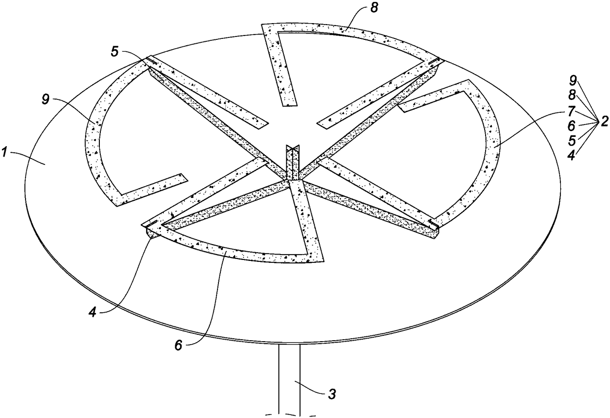
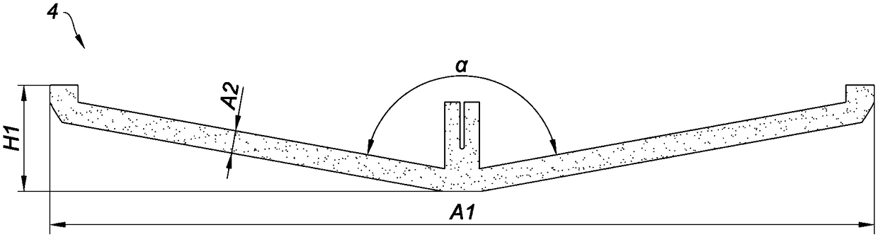
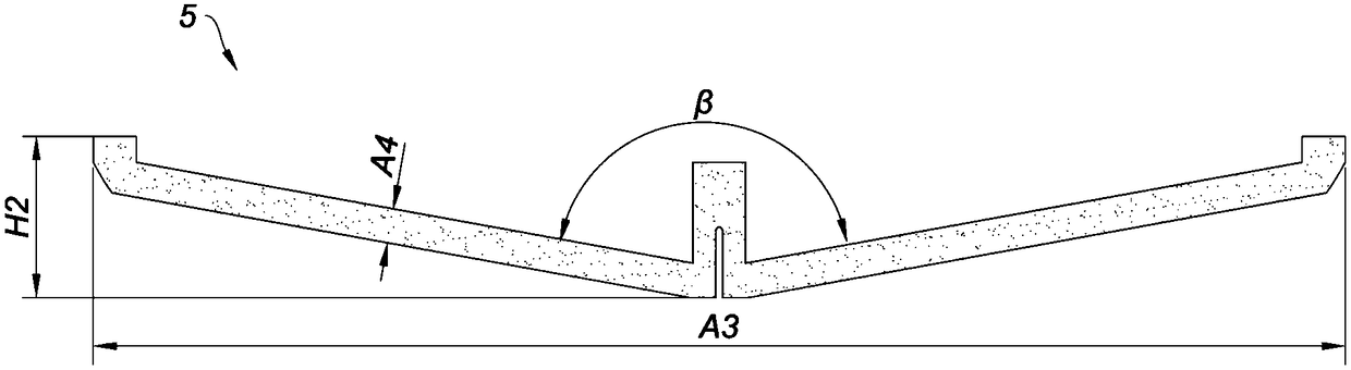
[0041] Such as figure 1As shown, a top-loaded broadband ceiling antenna described in this embodiment includes a reflector 1, an amplitude component 2, and a coaxial cable 3. The amplitude component 2 is installed on the reflector 1, and the coaxial cable The line 3 passes through the reflector 1 to feed the amplitude component 2, and the amplitude component 2 includes: a first microstrip line 4, a second microstrip line 5, a third microstrip line 6, a fourth microstrip line 7, The fifth microstrip line 8 and the sixth microstrip line 9; the first microstrip line 4 is V-shaped, and is in a plane called the first vibrator plane; the second microstrip line 5 is V-shaped , in a plane called the second oscillator plane; the third microstrip line 6, the fourth microstrip line 7, the fifth microstrip line 8 and the sixth microstrip line 9 are in a plane called the third microstrip line In the plane of the vibrator plane, the combination of the third microstrip line 6, the fourth mic...

Embodiment 2

[0053] The difference between this embodiment and Embodiment 1 is that: Figure 5 As shown, the first microstrip line 21, the second microstrip line 22, the third microstrip line 23, the fourth microstrip line 24, the fifth microstrip line 25 and the sixth microstrip line in this embodiment 26 is the copper clad on the PCB; wherein the first microstrip line 21 is the copper clad on the PCB 27, the second microstrip line 22 is the copper clad on the PCB 28, and the third microstrip line 23 , the fourth microstrip line 24 , the fifth microstrip line 25 and the sixth microstrip line 26 are copper clad on the PCB board 29 .

Embodiment 3

[0055] The difference between this embodiment and Embodiment 1 is that: Figure 6 As shown, the two ends of the V shape of the first microstrip line 31 in this embodiment also have a first vertical edge portion 32. At this time, the height of the first microstrip line 31 is 33mm, and the second microstrip line 33 The two ends of the V-shape also have a first vertical edge portion 34, and the height of the second microstrip line 33 is 33mm at this moment.


PUM


Abstract

The invention relates to a top-loaded broadband ceiling antenna. The top-loaded broadband ceiling antenna comprises a reflecting plate, an amplitude component and a coaxial cable, wherein the amplitude component is mounted on the reflecting plate; the coaxial cable feeds the amplitude component through the reflecting plate; the amplitude component comprises a first microstrip line, a second microstrip line, a third microstrip line, a fourth microstrip line, a fifth microstrip line and a sixth microstrip line; the first microstrip line is V-shaped, and is in a plane called first oscillator plane; the second microstrip line is V-shaped, and is in a plane called second oscillator plane; the third, fourth, fifth and sixth microstrip lines are in a plane called third oscillator plane; the firstmicrostrip line and the second microstrip line are connected at the respective V-shaped bottoms; the first microstrip line is connected with the third microstrip line and the fifth microstrip line; and the second microstrip line is connected with the fourth microstrip line and the sixth microstrip line. The top-loaded broadband ceiling antenna has the characteristics of simple processing process,easiness in processing, low cost, contribution to the development of enterprises and the like.

Description

technical field [0001] The invention relates to the technical field of communication, in particular to a top-loaded broadband ceiling antenna. Background technique [0002] Ceiling antenna is the main type of antenna used for signal coverage in indoor distribution system, and its performance directly affects system efficiency, communication quality and network investment. The ceiling antenna is generally composed of a radiator, a feeder and a grounding plate, wherein the grounding plate is connected to the wall, the radiator is located below the grounding plate, and the feeder passes through the grounding plate to connect to the radiator. According to actual needs, the radiator can be a vertically polarized radiator or a horizontally polarized radiator, or a vertically polarized radiator and a horizontally polarized radiator can be used at the same time. [0003] Conventional ceiling antennas mostly adopt a single-cone vibrator scheme or a double-cone vibrator scheme. At p...

Claims


Application Information

Patent Timeline
Patent Type & Authority Applications(China)
IPC IPC(8): H01Q1/38H01Q1/50H01Q5/20H01Q5/307H01Q19/10H01Q1/00
CPCH01Q1/38H01Q1/007H01Q1/50H01Q5/20H01Q5/307H01Q19/104
Inventor 郑洪振孙凯陆毅华
Owner FOSHAN CITY EAHISON COMM
Why Eureka
Try Eureka