
Correction control circuit and control method of ballistic correction projectile based on permanent magnet generator

A permanent magnet generator and control circuit technology, which is applied in the fields of controlling generators through magnetic field changes, electrical digital data processing, special data processing applications, etc. and other problems to achieve the effect of improving efficiency, improving accuracy, and saving projectile space

Inactive Publication Date: 2018-07-27
XIAN UNIV OF TECH
View PDF4 Cites 2 Cited by
  • Summary
  • Abstract
  • Description
  • Claims
  • Application Information

AI Technical Summary

Problems solved by technology

[0004] The purpose of the present invention is to provide a correction control circuit for ballistic correction projectiles based on permanent magnet generators, which solves the problems of complex structure, large space occupation of projectile body, slow correction and adjustment speed, and insufficient power supply of projectiles existing in the correction technology of traditional correction projectiles. question

Method used


Image

  • Correction control circuit and control method of ballistic correction projectile based on permanent magnet generator
  • Correction control circuit and control method of ballistic correction projectile based on permanent magnet generator
  • Correction control circuit and control method of ballistic correction projectile based on permanent magnet generator

Examples


Embodiment Construction

[0032] The present invention will be described in detail below in conjunction with the accompanying drawings and specific embodiments.

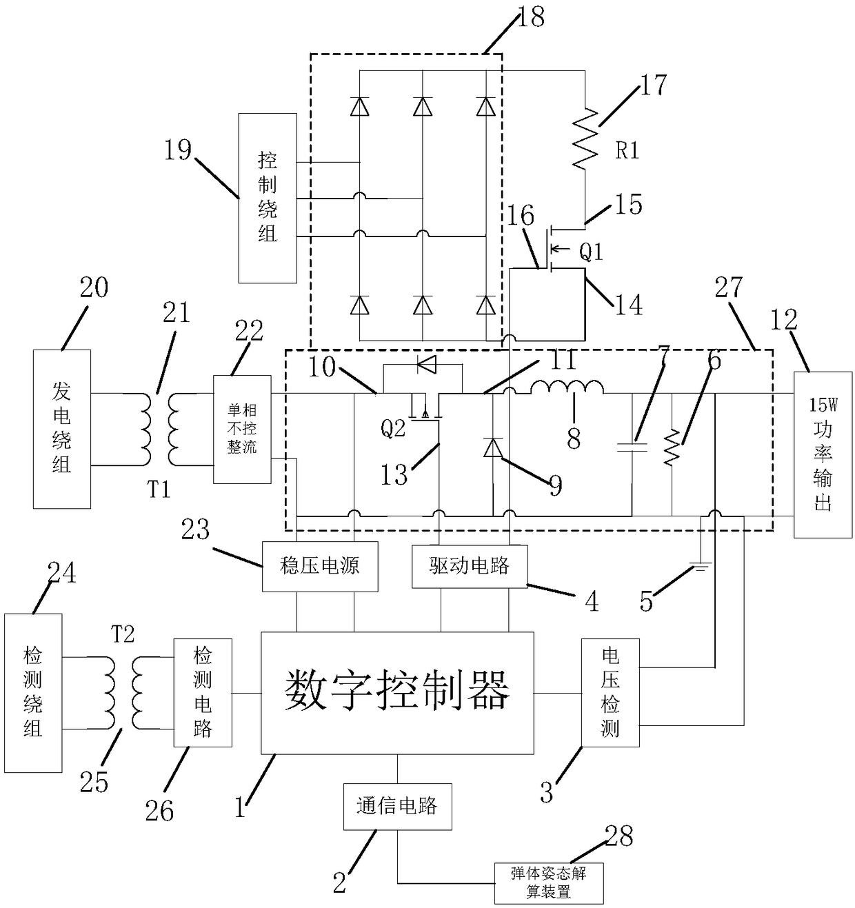
[0033] The correction control circuit of the ballistic correction bomb based on the permanent magnet generator of the present invention, the circuit diagram is as follows figure 1 As shown, it includes the generating winding 20, the three-phase control winding 19 and the detection winding 24 connected on the permanent magnet generator, the generating winding 20 is connected with the isolation transformer a21, and the isolation transformer a21 is connected with the single-phase uncontrolled rectification circuit 22, and the single-phase uncontrolled rectification circuit 22 is connected The output positive pole of the controlled rectification circuit 22 is connected to the positive pole of the DC-DC circuit 27, and the output positive pole of the single-phase non-controlled rectification circuit 22 is also connected with the regulated power sup...


PUM


Abstract

The invention discloses a correction control circuit of a ballistic correction projectile based on a permanent magnet generator. A power generation winding is connected with a single-phase uncontrolled rectifier circuit, the single-phase uncontrolled rectifier circuit is connected with a DC-DC circuit and is also connected with a stabilized power supply and then is connected with a digital controller; the output of the control winding is connected with a three-phase uncontrolled rectifier circuit and is connected with a load circuit through a second power switching tube; and a detection winding is connected with the digital controller through a detection circuit, and the digital controller is connected with a projectile posture resolver through a communication circuit. The invention further discloses a correction control method of the circuit. The method comprises the following steps: firstly recording, by the digital controller, a target location of the projectile, after the projectile is emitted, the correction system is powered on, measuring, by the digital controller, the rotating speed of the generator through the detection winding, calculating the deviation between the actualtrajectory and a predetermined trajectory, and finally, correcting, by the digital controller, the trajectory of the projectile in combination with the deviation and the rotating speed of the generator. By adoption of the correction control circuit and control method disclosed by the invention, the accuracy and rapidity of the correction process are improved.

Description

technical field [0001] The invention belongs to the technical field of computer application power electronics, and relates to a correction control circuit and a control method of a ballistic correction projectile based on a permanent magnet generator. Background technique [0002] In the context of the application requirements of modern warfare, along with fierce competition, how to improve the shooting accuracy of shells and reduce ammunition consumption has become a key issue in improving the practicability of ammunition. Therefore, ballistic correcting ammunition has emerged as the times require. It has the advantages of low cost, long range, and mass production, and the ballistic correction bomb is extremely suitable for the needs of modern warfare. At present, the development of domestic correction missile correction technology is relatively slow, and some progress has been made in the technical aspects of completing two-dimensional ballistic correction functions based ...

Claims


Application Information

Patent Timeline
Patent Type & Authority Applications(China)
IPC IPC(8): H02P9/30G06F17/50
CPCG06F30/20H02P9/30
Inventor 冷朝霞刘庆丰李培东
Owner XIAN UNIV OF TECH
Learn More