
Gantry Machine Tool for Fine Machining

A gantry machine tool and fine processing technology, applied in metal processing machinery parts, metal processing, metal processing equipment and other directions, can solve problems such as the inability to meet people's processing speed, efficiency and precision requirements, to ensure good rate and processing efficiency. , to ensure a stable effect

Active Publication Date: 2020-06-26
上海欧博自控技术装备有限公司
View PDF3 Cites 0 Cited by
  • Summary
  • Abstract
  • Description
  • Claims
  • Application Information

AI Technical Summary

Problems solved by technology

[0002] In modern machinery manufacturing, in addition to cutting, the methods of workpiece processing include casting, forging, welding, stamping, extrusion, etc., but when processing workpieces with higher precision requirements and finer surface roughness requirements, Traditional processing concepts can no longer meet people's requirements for processing speed, efficiency and precision, and usually need to be processed on CNC machine tools that perform fine processing
[0003] As the country's fine processing requirements for large parts are getting higher and higher, some current processing machine tools have been difficult to meet the current needs. In order to improve the processing efficiency and processing accuracy of such complex products, craftsmen have been looking for more efficient and precise machines. Processing method

Method used


Image

  • Gantry Machine Tool for Fine Machining
  • Gantry Machine Tool for Fine Machining
  • Gantry Machine Tool for Fine Machining

Examples


Embodiment Construction

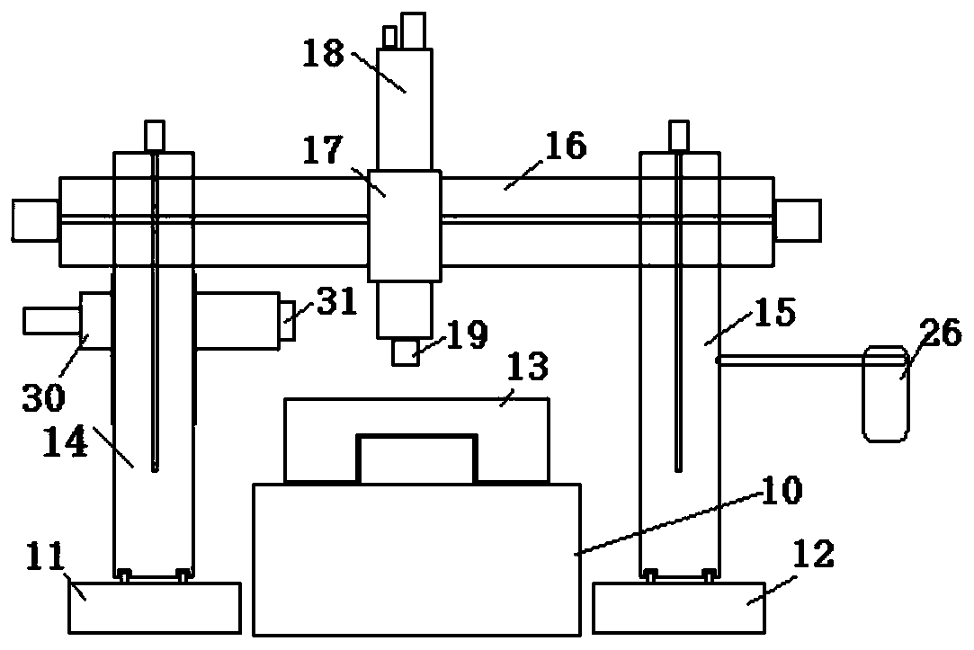
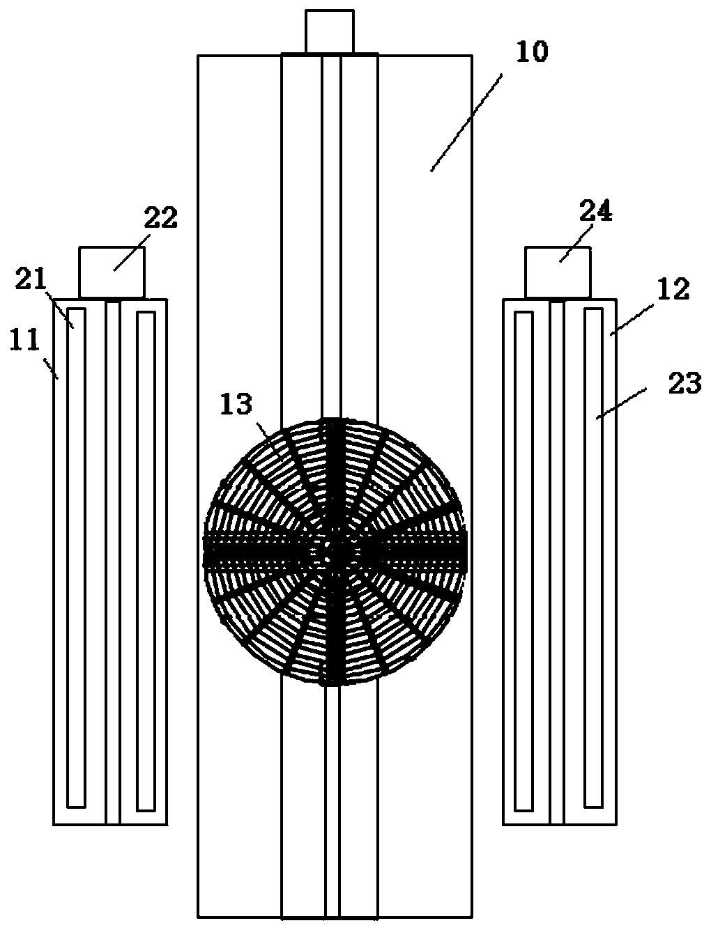
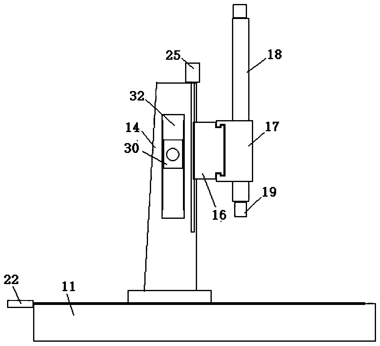
[0025] see Figure 1 to Figure 3 , shows one embodiment of the gantry machine tool for fine processing of the present invention.

[0026] In this embodiment, the gantry machine tool for fine processing includes a workpiece table 10, the two sides of the workpiece table 10 are respectively provided with a parallel left base 11 and a right base 12, and the top of the workpiece table 10 is provided with a rotating fixture 13.

[0027] Wherein, the left base 11 is provided with a left column 14 that can slide back and forth relative to each other, and the right base 12 is provided with a right column 15 that can slide back and forth relatively, and the left column 14 and the right column 15 can be carried out during sliding. synchronously, and the front side of described left column 14 and right column 15 is provided with the crossbeam 16 that can slide up and down relatively, and the front side of described crossbeam 16 is provided with the slide table 17 that can slide left and...


PUM


Abstract

A gantry machine tool for elaborate machining comprises a workpiece table; the two sides of the workpiece table are provided with a left base and a right base correspondingly; a rotating clamp is arranged above the workpiece table; a left stand column capable of relatively sliding forwards and backwards is arranged on the left base; the right base is provided with a right stand column capable of relatively sliding forwards and backwards; the front sides of the left stand column and the right stand column are provided with a cross beam capable of relatively sliding up and down; a sliding tablecapable of relatively sliding leftwards and rightwards is arranged on the front side of the cross beam, and is used for a telescopic column to penetrate; a machining head for machining a workpiece isarranged at the bottom end of the telescopic column; a side machining table is further arranged on the left stand column; a containing part is arranged on the middle portion of the left stand column;the two sides of the containing part are provided with rack slide rails; the side machining table can slide up and down along the rack slide rails on the two sides; and a telescopic side machining head is arranged on the inner side of the side machining table. Thus, the gantry machine tool for elaborate machining is convenient to operate and capable of providing elaborate machining for large partsso as to meet the requirements improved day by day.

Description

technical field [0001] The invention relates to the technical field of fine processing machine tools, in particular to a gantry machine tool for fine processing. Background technique [0002] In modern machinery manufacturing, in addition to cutting, the methods of workpiece processing include casting, forging, welding, stamping, extrusion, etc., but when processing workpieces with higher precision requirements and finer surface roughness requirements, Traditional processing concepts can no longer meet people's requirements for processing speed, efficiency and precision, and usually need to be processed on CNC machine tools that perform fine processing. [0003] As the country's fine processing requirements for large parts are getting higher and higher, some current processing machine tools have been difficult to meet the current needs. In order to improve the processing efficiency and processing accuracy of such complex products, craftsmen have been looking for more efficie...

Claims


Application Information

Patent Timeline
Patent Type & Authority Patents(China)
IPC IPC(8): B23Q1/01B23Q3/06
CPCB23Q1/012B23Q3/06B23Q39/026
Inventor 罗旭
Owner 上海欧博自控技术装备有限公司
Learn More