Self-pulsation stirrer for hot metal desulfurization

A technology for desulfurization of molten iron and agitator, which is applied to mixers with rotary stirring devices, chemical instruments and methods, transportation and packaging, etc. In order to improve the kinetic conditions of molten iron KR stirring desulfurization and the economic indicators of desulfurization technology, shorten the desulfurization reaction time, and improve the reaction speed and utilization rate

Active Publication Date: 2019-11-08
武汉钢铁有限公司
View PDF4 Cites 0 Cited by
  • Summary
  • Abstract
  • Description
  • Claims
  • Application Information

AI Technical Summary

Problems solved by technology

(3) Tangential flow, in a container without baffles, the fluid rotates around the stirring shaft. When the flow velocity is high, the fluid will form a vortex. At this time, the flow of the fluid from the circumference of the paddle to the paddle area is very small. poor mixing
The Chinese patent "KR Powder Spraying Melt Desulfurization Agitator, Application Publication No.: CN106702071A" discloses a stirring body with stirring blades arranged in the lower part, and first and second hubs are horizontally fixed on the upper and lower sides of the stirring blades, wherein The first hub is provided with nozzles, through which nitrogen gas is blown in to increase the stirring force, reduce the temperature of the stirring device, prolong the service life, and improve the desulfurization efficiency. There may be stirring holes on the stirring blades, but the specific structure and opening method of the stirring holes are not described. , and did not explain its specific performance, but the magnesium desulfurizer KR described in the patent specification is somewhat impractical for stirring desulfurization, because metal magnesium is easy to gasify at high temperature, and it is impossible to realize the stirring desulfurization after the molten iron level is added, but it is sprayed into the iron through the nozzle Magnesium desulfurization reaction can be realized in deep water
However, due to the limitation of high temperature, high-power stirring, intermittent production and other working conditions of mechanical stirring desulfurization of molten iron, many improvement measures studied are difficult to implement stably in actual production. Power impact also seriously affects the safety and stability of the mixing device; the high temperature and strong erosion and wear of the wall-attached baffle and the thermomechanical stress damage under intermittent working conditions seriously affect the reliability and stability of the wall-attached baffle; The air injection between the blades is affected by the sealing reliability of the rotary joint, which seriously threatens the stability of the air injection pressure and the reliability of the air injection; the large eccentric thrust of the eccentric stirring restricts the stable implementation of the eccentric parameters, and also threatens the smoothness of the mixing process and desulfurization equipment security, etc.

Method used


Image

  • Self-pulsation stirrer for hot metal desulfurization
  • Self-pulsation stirrer for hot metal desulfurization
  • Self-pulsation stirrer for hot metal desulfurization

Examples


Embodiment 1

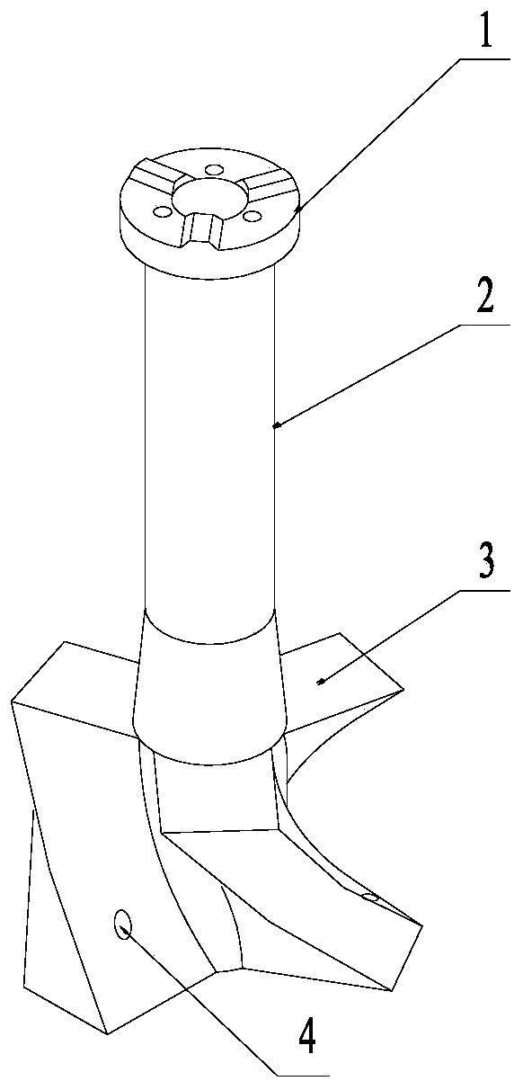
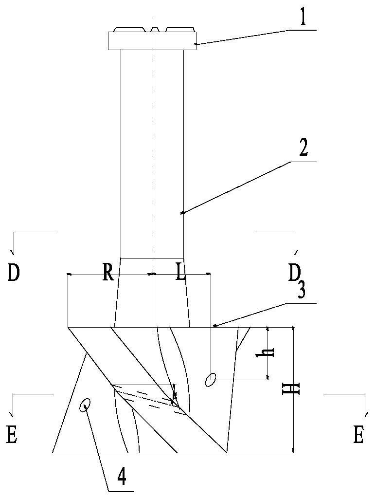
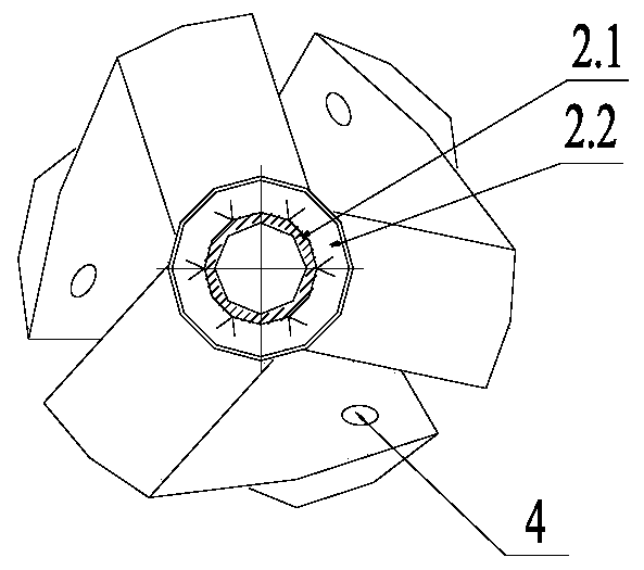
[0029] No matter how much the number of stirring blades 3 is (two, three or four all can be, as figure 2 , Figure 7 shown), each of the stirring blades 3 is provided with a flow field pulse interference through hole 4, and the flow field pulse interference through hole 4 is inclined downward along the stirring rotation circumference, and the downward inclination angle α is 5-20° ( Preferably 10°), in addition, the inner wall of each flow field pulse interference through hole 4 is wrapped with a stirring blade core refractory castable lining 3.2. The area of ​​each flow field pulse interference through hole 4 is 2~10% (preferably 6%) of the area of ​​the iron surface of the stirring blade 3, and the center point of the flow field pulse interference through hole 4 on the stirring blade 3 is far from the stirring blade 3 The distance h of the upper end surface is 1 / 3~2 / 3 (preferably 1 / 2) of the height H of the stirring blade 3, and the distance L between the central point of t...

Embodiment 2

[0031] The difference between embodiment 2 and embodiment 1 is: when the number of stirring blades is an even number of four or more than four, as Figure 5 As shown, the flow field pulse interference through holes 4 can also be provided on the stirring blade 3 at intervals (such as Figure 6 shown), that is, the stirring blade 3 adjacent to the stirring blade 3 provided with the flow field pulse interference through hole 4 is not provided with the flow field pulse interference through hole 4, that is, not all the stirring blades 3 have flow field pulse interference The through-holes 4 and the flow field pulse interference through-holes 4 provided at intervals can be arranged obliquely downward along the stirring rotation circumference, and the downward inclination angle α is 5-20° (preferably 10°).

Embodiment 3

[0033] The difference between embodiment 3 and embodiment 2 is that: the flow field pulse interference through-hole 4 is arranged horizontally along the stirring rotation circumferential direction.


PUM


Abstract

The invention discloses a self-pulse stirrer for molten iron desulfurization, which comprises a stirrer connecting flange, a stirring shaft and stirring blades fixed on the outer periphery of the stirring shaft and evenly distributed around the circumference of the stirring shaft; the stirring The shaft includes a stirring shaft core and a stirring shaft core refractory castable lining, and the stirring blades include a stirring blade core and a stirring blade core refractory casting material lining; The flow field pulse interference through holes of the leaves and the prime number flow field pulse interference through holes are all inclined downward along the stirring rotation circumference, and the downward inclination angle α is 5-20°. It can suppress the tangential flow of stirring, strengthen the axial and radial flow of stirring, achieve the effect of reducing the forced vortex area, expanding the free vortex area and improving the mixing characteristics of stirring. It has simple structure, easy preparation, sufficient stirring and mixing, and desulfurization. High efficiency and long service life.

Description

technical field [0001] The invention relates to the field of hot metal pretreatment, in particular to a self-pulse agitator for hot metal desulfurization. Background technique [0002] The hot metal KR mechanical stirring desulfurization method uses a single-layer cross-arranged agitator with rectangular or inverted trapezoidal blades lined with refractory materials to vertically immerse in the molten iron along the center of the molten iron tank for rotation and agitation, so that the molten iron surface generates a vortex. A certain amount of desulfurizer is added to the surface of molten iron by the feeder, and the desulfurizer floating on the surface of the molten iron is drawn into the molten iron by the vortex, and is discharged and floated under the action of centrifugal force and buoyancy force to realize the circulation of the desulfurizer in the molten iron Entrainment and floating, the purpose of desulfurization of molten iron is achieved through the circulation, ...

Claims


Application Information

Patent Timeline
Patent Type & Authority Patents(China)
IPC IPC(8): C21C1/02C21C7/064B01F7/00
CPCC21C1/02C21C7/064B01F27/11251B01F2101/26
Inventor 欧阳德刚李明晖齐江华
Owner 武汉钢铁有限公司
Why Eureka
Try Eureka