Performance test table for compressor and using method

A technology of compressors and test benches, which is applied in the field of compressors, can solve the problems of increasing the cost of experiments and single applicability of test equipment, achieve high applicability, reduce the possibility of high temperature aging cracking, and reduce the effect of test errors

Pending Publication Date: 2018-07-31
浙江商业机械厂有限公司
View PDF0 Cites 5 Cited by
  • Summary
  • Abstract
  • Description
  • Claims
  • Application Information

AI Technical Summary

Problems solved by technology

Improve the experiment cost invention, also make the applicability of the test equipment very single

Method used


Image

  • Performance test table for compressor and using method
  • Performance test table for compressor and using method
  • Performance test table for compressor and using method

Examples


Embodiment 1

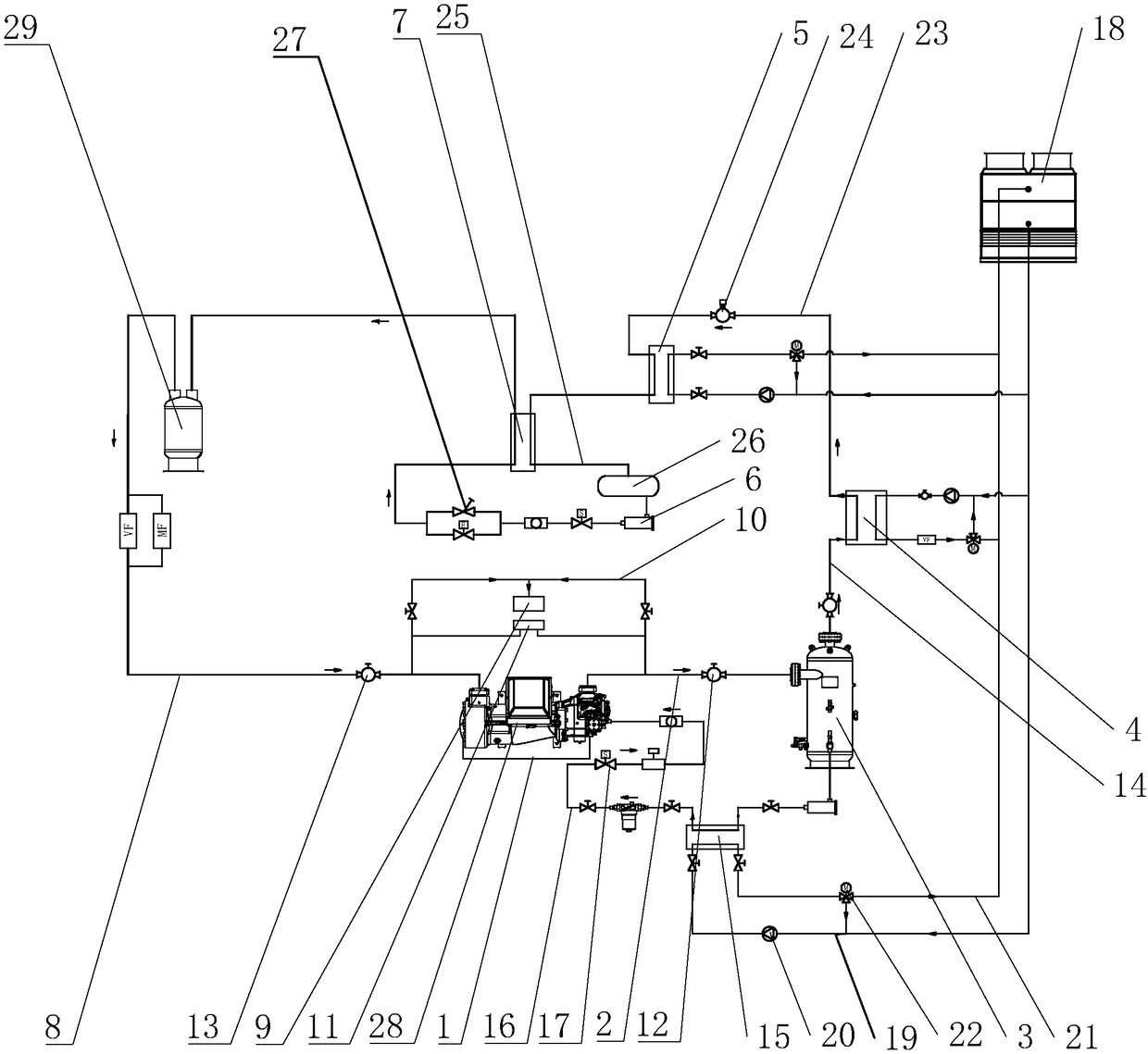
[0048] Such as figure 2 As shown, a performance test bench for a compressor includes a frame 1 on which an exhaust pipe 2, an oil separator 3, a calorimeter 4, a condenser 5, a dry filter 6, Evaporative condenser 7, gas-liquid separator 29 and suction pipe 8. A vacuum pump 9 is installed on the frame 1, and an exhaust pipe 10 is connected between the exhaust pipe 2 and the suction pipe 8 and the vacuum pump 9. Both the exhaust pipe 2 and the suction pipe 8 are provided with a pressure controller 11, the exhaust pipe 2 is provided with an exhaust valve 12 for controlling the opening and closing of the exhaust pipe 2, and the suction pipe 8 is provided with a pressure controller 12 for controlling the suction pressure. Pipe 8 opens and closes suction valve 13.

[0049] The exhaust pipe 2 is connected to the exhaust port of the compressor 28 , and one end of the exhaust pipe 2 is connected to the liquid inlet end of the oil separator 3 , and the first connecting pipe 14 is con...

Embodiment 2

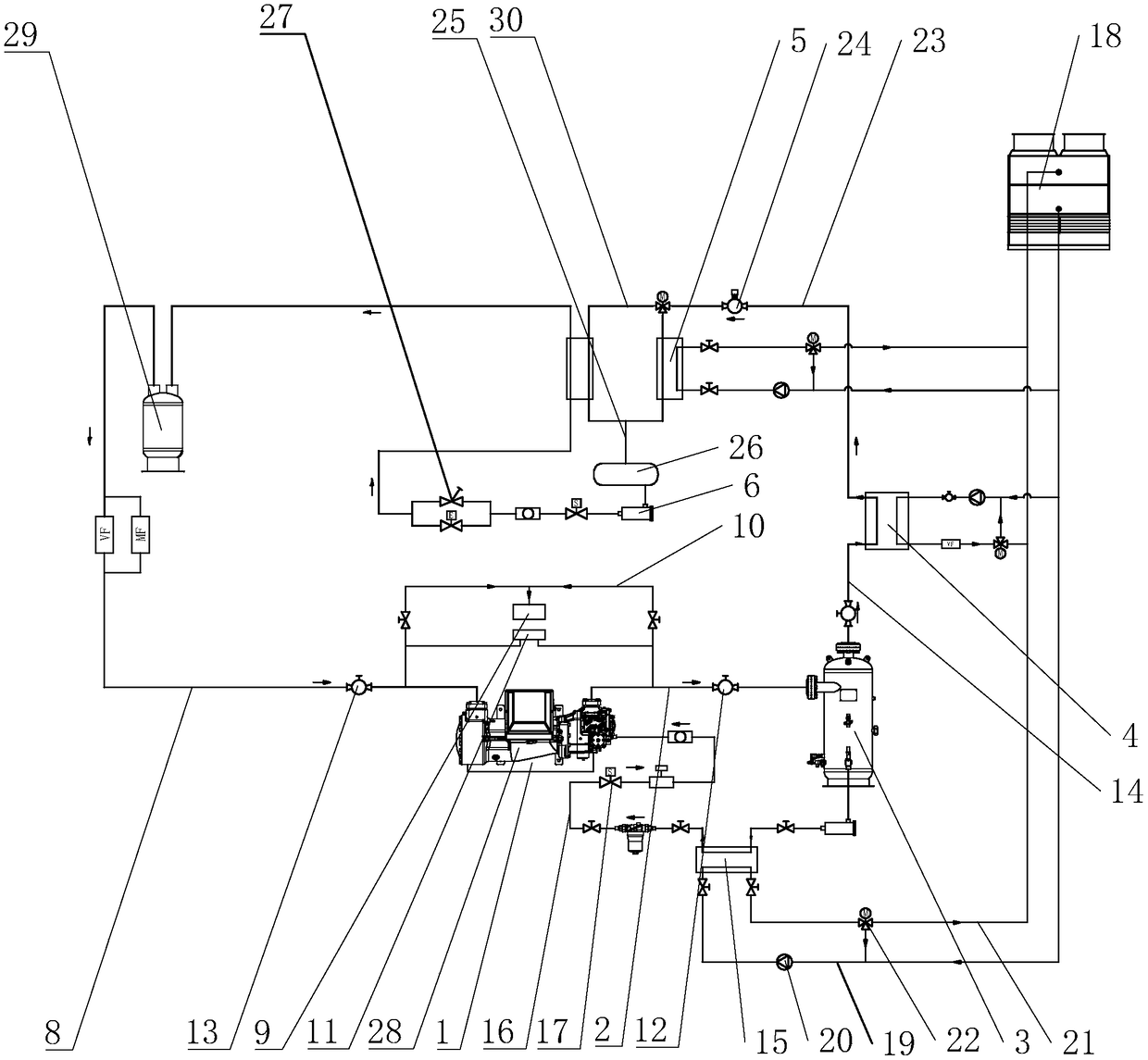
[0060] The difference between embodiment two and embodiment one is:

[0061] Such as image 3 As shown, the second connecting pipe 23 is directly connected to the liquid inlet end of the dry filter 6 . One side of the second connecting pipe 23 is connected with a third connecting pipe 30 , the third connecting pipe 30 is connected to the liquid inlet end of the evaporative condenser 5 , and the liquid outlet end of the evaporative condenser 5 is connected to the liquid inlet end of the fourth connecting pipe 25 .

[0062] Part of the high-temperature and high-pressure refrigerant gas discharged from the compressor 28 enters the condenser 5 for condensation, and the other part enters the evaporative condenser 5 for condensation, and becomes a supercooled liquid after being condensed, and enters the evaporative condenser 5 after being throttled by the electronic expansion valve 27. After absorbing heat in the evaporative condenser 5, the overheated gas is sucked by the compress...

Embodiment 3

[0064] S1. Connect the discharge pipe 2 to the discharge port of the compressor 28, connect the suction pipe 8 to the suction port of the compressor 28, and connect the oil supply pipe 16 to the oil supply port of the compressor 28;

[0065] S2. Connect the high-pressure connection pipeline of the compressor 28 under test to the high-pressure pressure measurement point and the discharge temperature measurement point, and the 28 low-pressure connection pipelines of the compressor under test to connect the low-pressure pressure measurement point and the discharge temperature measurement point. The air in the machine 28 is exhausted;

[0066] S3, open the exhaust valve 12, the suction valve 13, and the oil supply valve 17 in sequence;

[0067] S4, making the regulating valve 24 reach a prescribed opening degree;

[0068] S5, turn on the water pump 20 and the compressor under test 28, and gradually open the loading solenoid valve on the compressor under test 28;

[0069] S5. Obs...


PUM


Abstract

The invention discloses a performance test table for a compressor. The performance test table comprises a machine frame. An exhaust pipe, an oil separator, a calorimeter, a gas-liquid separator and anair suction pipe which are sequentially connected are installed on the machine frame, the exhaust pipe is connected with an exhaust port of the compressor, and the air suction pipe is connected withan air suction port of the compressor. The machine frame is further provided with a condenser, a drying filter and an evaporation condenser which are sequentially connected. The air outlet end of thecalorimeter is connected with a second connection pipe, the condenser is located on the second connection pipe, the liquid outlet end of the second connection pipe is connected with the liquid inlet end of the drying filter, the second connection pipe is provided with an adjusting valve, the liquid outlet end of the drying filter is connected with the liquid inlet end of the evaporation condenser,an electronic expansion valve is arranged between the drying filter and the evaporation condenser, and the air outlet end of the evaporation condenser is connected with the air inlet end of the gas-liquid separator. One test table can be applicable to various types of compressors without frequently replacing the condenser, the test table has the high applicability, and the cost per use is reduced.

Description

technical field [0001] The invention relates to a compressor, in particular to a performance test bench for a compressor and a usage method. Background technique [0002] Compared with ordinary compressors, volumetric enthalpy-increasing compressors (such as screw compressors, gas-injecting enthalpy-increasing scroll compressors, etc.) are more and more widely used due to their advantages of high energy efficiency, wide temperature range, and high reliability. Therefore, it is of great significance to research and improve the refrigeration performance of this kind of compressor. However, there are certain defects in the current test of cooling capacity, which leads to large deviations in the test of cooling capacity of volumetric enthalpy-increasing compressors, which is not conducive to guiding the high-efficiency development of this type of compressor. [0003] From GB / T5773-2004 volumetric refrigerant compressor performance test method, it can be known that for the cooli...

Claims


Application Information

Patent Timeline
Patent Type & Authority Applications(China)
IPC IPC(8): F04B51/00
CPCF04B51/00
Inventor 袁海淦余有发
Owner 浙江商业机械厂有限公司
Why Eureka
Try Eureka