Eureka AIR delivers breakthrough ideas for toughest innovation challenges, trusted by R&D personnel around the world.

Data transmission method and apparatus

A transmission method and data technology, applied in the field of communication, can solve the problems of reduced business transmission flexibility, impact, poor broadband utilization, etc., and achieve the effect of reducing data transmission costs

Active Publication Date: 2018-07-31
ZTE CORP
View PDF9 Cites 3 Cited by
  • Summary
  • Abstract
  • Description
  • Claims
  • Application Information

AI Technical Summary

Problems solved by technology

Unable to meet the needs of low-latency services
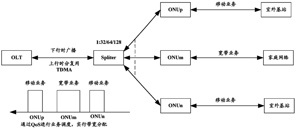
[0006] In order to reduce the transmission delay of the PON network, a fixed bandwidth allocation mechanism can be used to allocate fixed time slots to different service signals, and at the same time reduce the time slot interval between services and the length of the allocated time slot bandwidth to reduce transmission delay. To meet some low-latency data transmission requirements, but because this method requires a fixed service bandwidth, the flexibility of service transmission may be reduced; and when the service bandwidth is less than the fixed bandwidth allocated by the system, there will be idle time slots, Limited bandwidth resources are wasted, so this method has poor bandwidth utilization
It is also possible to reduce the delay by optimizing the DBA algorithm, increase the priority of low-latency service signals, and realize fast forwarding, but this method of reducing delay will affect the original high-priority business, and its delay reduction value is also limited
Another method is to add a pair of uplink and downlink wavelengths to the existing PON system, and use independent wavelength channels to transmit low-latency services. This method is the simplest and feasible. Since the service wavelengths are different, it will not affect the main service. However, in order to transmit low-latency services, the system needs to add an additional set of transmitting and receiving devices, especially the need to add independent optical path transmitting and receiving devices, which requires large-scale improvements to the existing network, and even needs to be directly replaced with new ones. system, resulting in an increase in additional costs
[0007] For the technical problem of high cost of transmitting data with different delays in the passive optical network, no effective solution has been proposed so far

Method used


Image

  • Data transmission method and apparatus
  • Data transmission method and apparatus
  • Data transmission method and apparatus

Examples


Embodiment 1

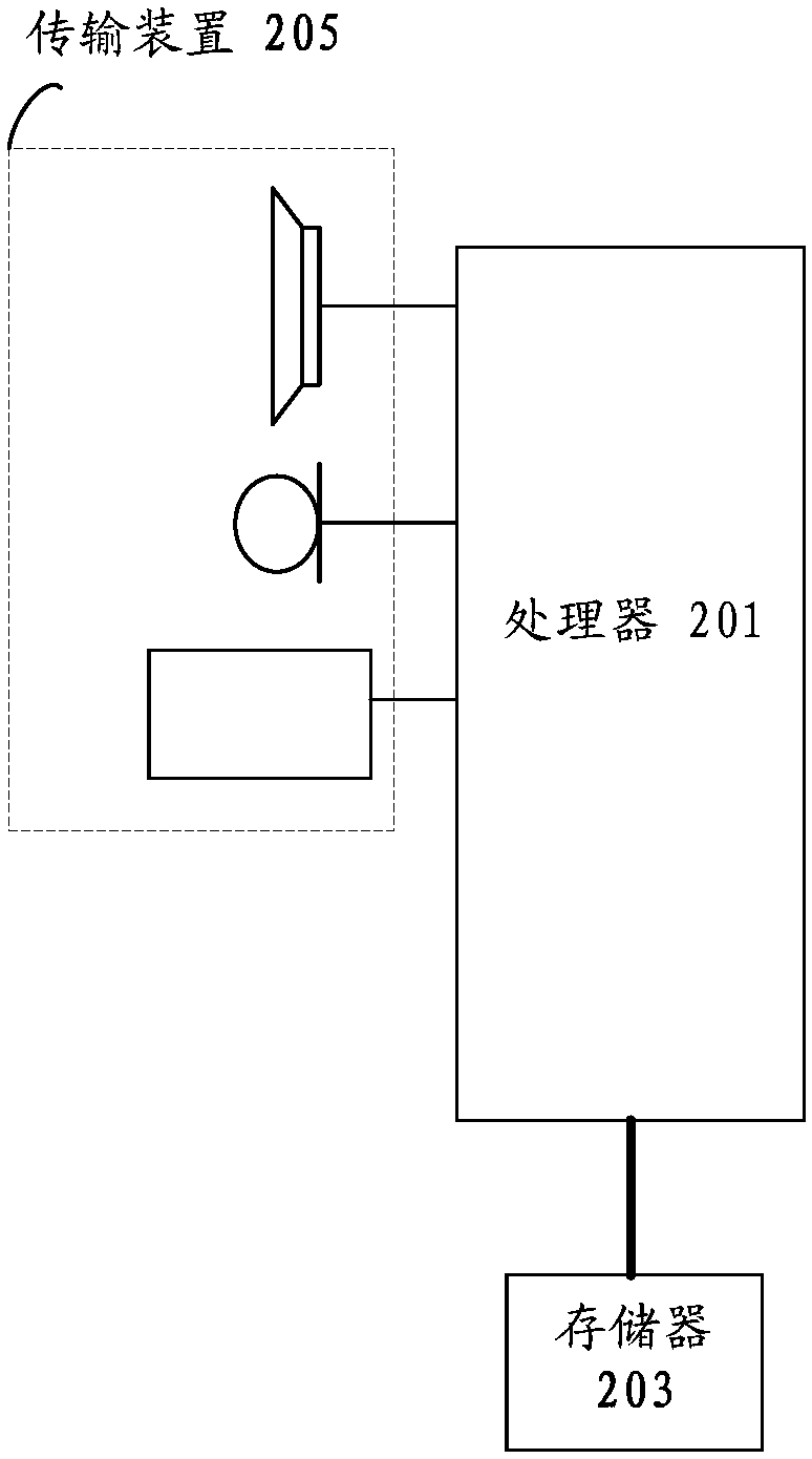
[0065] The method embodiment provided in Embodiment 1 of the present application may be executed in a mobile terminal, a computer terminal, or a similar computing device. Take running on a mobile terminal as an example, such as figure 2 As shown, the computer terminal may include one or more (only one is shown in the figure) processors 201 (the processors 201 may include but not limited to processing devices such as microprocessor MCU or programmable logic device FPGA, etc.), for storing Data storage 203, and transmission means 205 for communication functions. Those of ordinary skill in the art can understand that, figure 2 The shown structure is only for illustration, and it does not limit the structure of the above-mentioned electronic device.

[0066] The memory 203 can be used to store software programs and modules of application software, such as program instructions / modules corresponding to the control method of the device in the embodiment of the present invention, ...

Embodiment 2

[0162] The embodiment of the present invention also provides a data transmission device. The device is used to implement the above-mentioned embodiments and preferred implementation modes, and what has been described will not be repeated. As used below, the term "module" may be a combination of software and / or hardware that realizes a predetermined function. Although the devices described in the following embodiments are preferably implemented in software, implementations in hardware, or a combination of software and hardware are also possible and contemplated.

[0163] Figure 26 is a schematic diagram of a data transmission device according to an embodiment of the present invention. Such as Figure 26 As shown, the device may include: a receiving unit 261 and a transmitting unit 262 .

[0164] The receiving unit 261 is configured to obtain the first type of data and the second type of data to be sent, wherein the transmission delay allowed by the first type of data is le...

Embodiment 3

[0182] The embodiment of the invention also provides a storage medium. Optionally, in this embodiment, the above-mentioned storage medium may be configured to store program codes for performing the following steps:

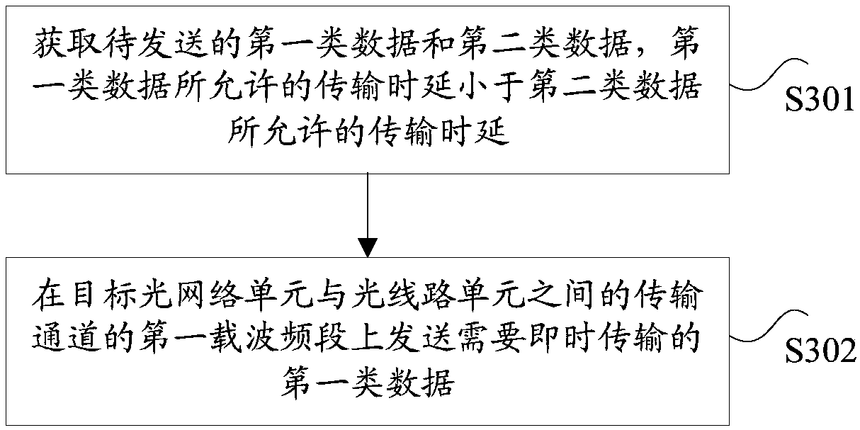
[0183] S11. Obtain the first type of data and the second type of data to be sent, wherein the transmission delay allowed by the first type of data is less than the allowed transmission delay of the second type of data;

[0184] S12. Send the first type of data that needs to be transmitted immediately on the first carrier frequency band of the transmission channel between the target optical network unit and the optical line unit, wherein the transmission channel allows simultaneous transmission of the first type of data and the second type of data, and the transmission The lowest frequency in the second frequency band used to transmit the second type of data on the channel is higher than the highest frequency in the first carrier frequency band.

[0185] Optionall...


PUM


Abstract

The invention provides a data transmission method and apparatus. The method comprises the following steps: obtaining a first type of data and a second type of data to be sent, wherein a transmission delay allowed by the first type of data is smaller than the transmission delay allowed by the second type of data; and sending first type of data that needs to be transmitted instantaneously on a firstcarrier frequency band of a transmission channel between a target optical line unit and an optical line unit, wherein the transmission channel allows the simultaneous transmission of the first type of data and the second type of data, and the lowest frequency in the second frequency band for sending the second type of data on the transmission channel is higher than the highest frequency in the first carrier frequency band. By adoption of the data transmission method and apparatus, the technical problem of high cost of transmitting data with different delays in a passive optical network is solved.

Description

technical field [0001] The present invention relates to the communication field, in particular, to a data transmission method and device. Background technique [0002] With the development of the Internet, IoT applications such as Internet of Vehicles, smart medical care, and smart home have been widely used. Mobile communication is not limited to communication between people, but is also moving towards communication between people and things and between things. Internet will become an inevitable trend. At present, the cellular-based narrowband Internet of Things NB-IOT (Narrow Band Internet of Things, NB-IOT) has become an important branch of the Internet of Everything. As an evolution technology of LTE, 4.5G wireless network not only has a peak rate of up to 1Gbps, but also means more connections based on cellular IoT, supports massive M2M (Machine to Machine) connections and ultra-low latency. Passive Optical Network (PON, referred to as Passive Optical Network) has the...

Claims


Application Information

Patent Timeline
IPC IPC(8): H04L5/00H04W72/04
CPCH04L5/0037H04L5/0039H04L5/0044H04L5/0094H04W72/0446H04W72/53H04L5/0003H04L5/14H04L5/0041H04Q11/0067H04Q2011/0084H04J14/007H04J14/0298
Inventor 陈雷黄新刚贺江艳李玉峰李明生
Owner ZTE CORP
Why Eureka
Eureka Blog
Learn More