Blade equipped with a cooling system, associated guide vanes assembly and associated turbomachine

A cooling system, turbine technology, applied in the direction of supporting elements of blades, engine cooling, turbine/propulsion cooling, etc., can solve the problems of air loss, inability to use cooling blades or turbines, cold air leakage, etc.

Active Publication Date: 2018-07-31
SAFRAN HELICOPTER ENGINES
View PDF3 Cites 0 Cited by
  • Summary
  • Abstract
  • Description
  • Claims
  • Application Information

AI Technical Summary

Problems solved by technology

[0008] However, this insert configuration results in a significant leakage of cold air at the interface between the insert and the inner meridian
The air that escapes due to this leak is lost (especially in the jet stream of the outflow of gas) and cannot be used to cool the blades or other parts of the turbine

Method used


Image

  • Blade equipped with a cooling system, associated guide vanes assembly and associated turbomachine
  • Blade equipped with a cooling system, associated guide vanes assembly and associated turbomachine
  • Blade equipped with a cooling system, associated guide vanes assembly and associated turbomachine

Examples


Embodiment Construction

[0036] The following embodiments are examples. Although the description refers to one or more embodiments, this does not necessarily mean that each reference refers to the same embodiment, or that the features are only applicable to a single embodiment. Individual features of different embodiments can also be combined to provide other embodiments. In the drawings, scales and proportions are not strictly observed, which is for the purpose of illustration and clarity.

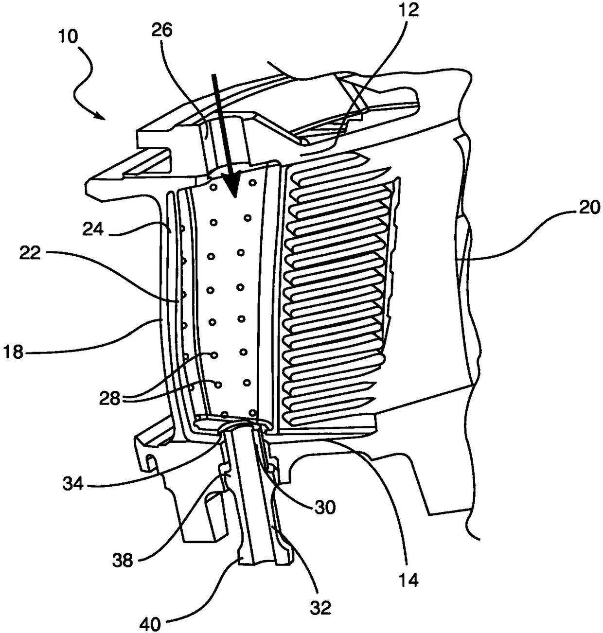
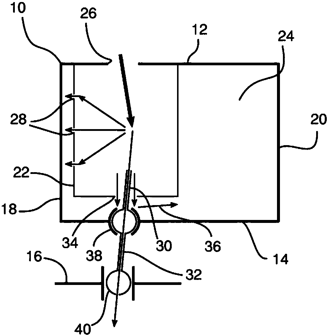
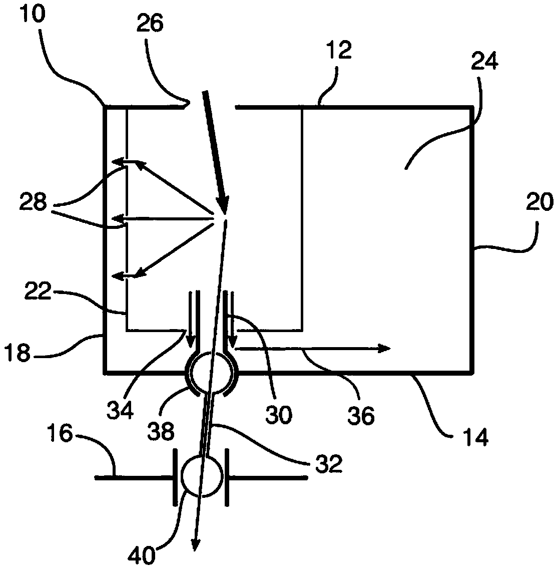
[0037] Figure 1 to Figure 3 ( figure 1 As a perspective view and figure 2 with image 3 As a cross-sectional view), the blade 10 of the guide vane assembly of the turbine is schematically shown. For example, the blade 10 arranged in a turbine includes a portion called the outer meridian 12 on the side of the combustion chamber (not shown) of the turbine, and a portion called the inner meridian 14 on the side of the central hub 16 of the turbine. The rotating part of the turbine rotates around the central hub. ...


PUM


Abstract

The invention relates to a blade of a turbomachine guide vanes assembly, which blade is equipped with a cooling system comprising an insert (22) arranged inside an internal cavity (24) of the said blade, connected to an inlet (26) for blade cooling air and designed to cool the surface of the internal cavity (24) of the blade, a bleed device configured to bleed some of the cooling air inside the insert (22) and designed to convey it to a central hub of the turbomachine. The bleed device comprises a bleed head (30) arranged in the internal cavity (24) of the blade and passing through an opening(34) of the insert, and configured to bleed some of the cooling air inside the insert (22).

Description

Technical field [0001] The invention relates to a blade of a guide vane assembly of a turbine. Specifically, the present invention relates to a blade of a guide vane assembly equipped with a cooling system for the blade and for other parts of the turbine. Background technique [0002] Generally, a turbine includes one or more compressor stages (such as a low-pressure compressor and a high-pressure compressor), a combustion chamber, and one or more turbine stages (such as a high-pressure turbine and a low-pressure turbine) from upstream to downstream. Upstream and downstream are defined relative to the normal gas flow direction (from upstream to downstream) in the outflow jet. [0003] The turbine converts the thermal and kinetic energy of the airflow from the combustion chamber into the required mechanical energy to drive the compressor and / or the rotor (for example, in the case of a helicopter). [0004] Turbines generally include one or more blade stages, each stage generally inc...

Claims


Application Information

Patent Timeline
Patent Type & Authority Applications(China)
IPC IPC(8): F01D5/18F01D9/06
CPCF01D5/188F01D9/065F05D2260/201Y02T50/60F01D5/18F01D9/02F01D25/246F02C7/18F05D2240/12F05D2240/81
Inventor 巴普蒂斯特·哈路英简-路克·布雷宁达米恩·拉伯尼
Owner SAFRAN HELICOPTER ENGINES
Why Eureka
Try Eureka