Shaft workpiece propping and clamping device

A shaft workpiece and top clamping technology, which is applied in the direction of clamping devices, positioning devices, metal processing machinery parts, etc., can solve the problems of reducing processing efficiency, not processing, and cannot process the parts where shaft workpieces are clamped, etc. Achieve the effects of improving processing efficiency and processing accuracy, stable and reliable clamping, and easy clamping and operation

Inactive Publication Date: 2018-08-03
重庆恒博机械制造有限公司
View PDF9 Cites 1 Cited by
  • Summary
  • Abstract
  • Description
  • Claims
  • Application Information

AI Technical Summary

Problems solved by technology

The disadvantage of this traditional one-clamp-one-top method is that the clamped part of the shaft workpiece cannot be processed. If the clamped part of the shaft workpiece is to be processed, the shaft workpiece must be unloaded and turned around. Secondary clamping, which not only reduces processing efficiency, but also affects processing accuracy
The tail top clamping device is connected with the rotating body through the fixer, the fixer ventilates and locks the positioning sleeve, clamps the workpiece on the positioning sleeve, the pneumatic tail top clamps the workpiece, and can complete the processing of any angle of the workpiece under the drive of the motor. Thus, the processing efficiency is improved, but the part of the workpiece clamped by the positioning sleeve is still not processed

Method used


Image

  • Shaft workpiece propping and clamping device
  • Shaft workpiece propping and clamping device
  • Shaft workpiece propping and clamping device

Examples


Embodiment Construction

[0021] The present invention will be further described below in conjunction with the accompanying drawings.

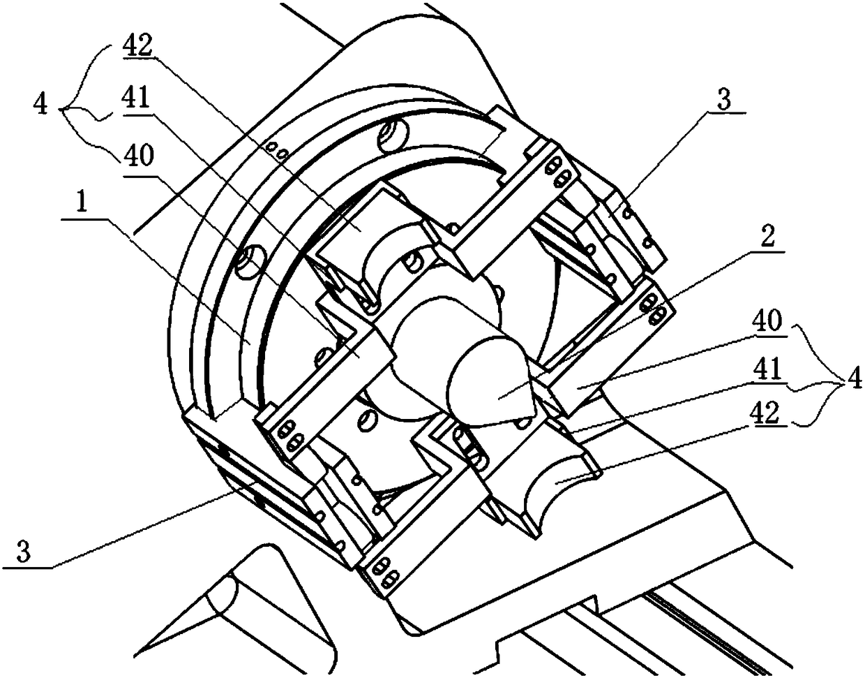
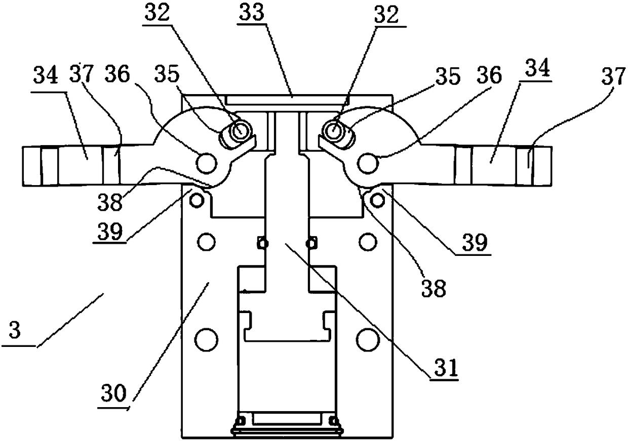
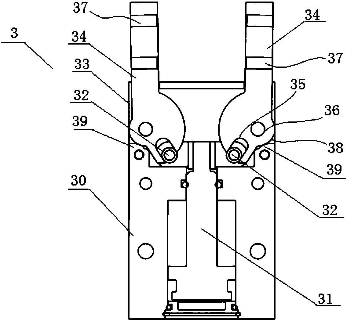
[0022] see Figure 1 to Figure 6 The top clamping device for a shaft workpiece shown includes a stepped disc seat 1 fixedly connected to the headstock or tailstock of the machine tool, and a top 2 protruding from the center of the disc seat. Its essential features are: A hydraulic overturn clamping mechanism is fixedly connected to the edge of the disc seat; the hydraulic overturn clamping mechanism includes two sets of hydraulic drive components 3 with the same structure and symmetrically arranged on the edge of the disc seat, and two pairs of The overturn clamping member 4 connected by two sets of hydraulic drive members.

[0023] One set of top clamping device of the hydraulic flip clamping mechanism is installed on the spindle box of the machine tool, and the other set of top clamping device is installed on the tailstock of the machine tool, which can not only cla...


PUM


Abstract

The invention relates to a shaft workpiece propping and clamping device which comprises a stepped disc seat and a propping tip, wherein the disc seat is fixedly connected onto a machine tool spindle box or tail sea; the propping tip extends out of the center of the disc seat. The shaft workpiece propping and clamping device is characterized in that a hydraulic overturning and clamping mechanism isfixedly connected with the edge of the disc seat, and comprises two sets of hydraulic driving components as well as two pairs of overturning and clamping components; the hydraulic driving componentsare of the same structure and symmetrically arranged on the edge of the disc seat; and the overturning and clamping components are correspondingly connected with the hydraulic driving components. Theshaft workpiece propping and clamping device provided by the invention has not only the clamping function of a conventional machine tool spindle box but also the propping function of a conventional machine tool tail seat; a shaft workpiece can be stably and reliably clamped; the simple and convenient clamping operation can be achieved; all parts of the shaft workpiece can be machined through one-time clamping; and the machining efficiency and the machining precision can be improved.

Description

technical field [0001] The invention relates to machine tools, in particular to a top clamping device for shaft workpieces. Background technique [0002] To process a shaft workpiece on a machine tool, the shaft workpiece must be stably clamped on the worktable of the machine tool. One end of the workbench of the machine tool is provided with a spindle box and the other end is provided with a tailstock, the spindle box is provided with a workpiece clamping mechanism, and the tailstock is provided with a top mechanism. When processing shaft workpieces, one end of the shaft workpiece is clamped on the workpiece clamping mechanism, and the other end is tightened by the top mechanism. As CN 204235151U announces "a lathe fixture when one clamp and one top clamping method is required in turning processing", it can simplify the clamping steps and reduce clamping actions. The three jaws with taper are fixed on the positioning plate with positioning screw holes through waist-shaped...

Claims


Application Information

Patent Timeline
Patent Type & Authority Applications(China)
IPC IPC(8): B23Q3/12B23Q3/00
CPCB23Q3/00B23Q3/12B23Q2703/04
Inventor 刘学贵
Owner 重庆恒博机械制造有限公司
Why Eureka
Try Eureka