Automatic robot

A robotic and automatic technology, applied in the direction of manipulators, manufacturing tools, etc., can solve the problems of low safety, hidden dangers, reduce the working efficiency of cutting robots, etc., and achieve the effect of simple structure and convenient operation.

Active Publication Date: 2018-08-03
苏州济和精密传动系统有限公司
View PDF7 Cites 7 Cited by
  • Summary
  • Abstract
  • Description
  • Claims
  • Application Information

AI Technical Summary

Problems solved by technology

However, the cutting robots currently on the market are inconvenient to assemble and replace the cutting blades during use, which affects the normal use of the cutting robots, thereby reducing the working efficiency of the cutting robots. In addition, the cutting blades of the existing cutting robots Exposed and without protective measures, low security, and there are large potential safety hazards

Method used


Image

  • Automatic robot
  • Automatic robot
  • Automatic robot

Examples


Embodiment Construction

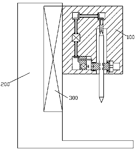
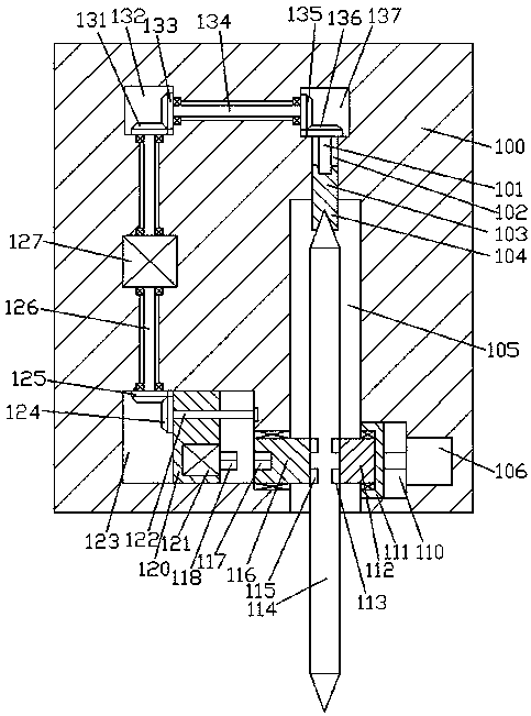
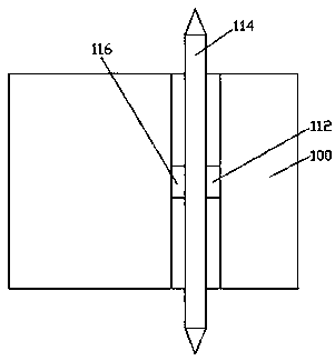
[0012] Combine below Figure 1-3 The present invention will be described in detail.

[0013] refer to Figure 1-3 , an automatic robot according to an embodiment of the present invention, comprising a cutting body 100, the cutting body is installed on the right end surface of the support base 200 through a lifting drive device 300, and an embedding cavity 105 is provided in the bottom end surface of the cutting body 100, A cutting blade 114 is rotatably installed in the embedding cavity 105, and a locking mechanism for locking and fitting with the cutting blade 114 is provided in the inner wall of the right side of the embedding cavity 105. A sliding cavity 123 is provided in the inner wall of the cutting machine body 100, and a left clamping joint 116 is installed in the wall between the sliding cavity 123 and the embedding cavity 105 for rotation and cooperation, and the left end surface of the left clamping joint 116 has a A spline chamber 117, a sliding block 120 is inst...


PUM


Abstract

The invention discloses an automatic robot. The automatic robot comprises a cutting machine body, and the cutting machine body is arranged on the right end surface of a supporting base through a lifting driving device; an embedding cavity is formed in the end surface of the bottom of the cutting machine body; a cutting blade is arranged in the embedding cavity in a rotating fit mode; a clamping mechanism used for being connected to the cutting blade in a locking fit mode is arranged in the inner wall of the right side of the embedding cavity; a sliding cavity is formed in the position, on theleft side of the embedding cavity, of an inner wall body of the cutting machine; a left clamping joint is arranged in a wall body between the sliding cavity and the embedding cavity in a rotating fitmode; a spline cavity is formed in the left end surface of the left clamping joint; a sliding block is arranged in the sliding cavity in a sliding fit mode; a first motor is fixedly arranged in the right end surface of the sliding block; and a spline shaft which is in spline fit connection with the spline cavity is arranged on the right end of the first motor in a power fit mode.

Description

technical field [0001] The invention relates to the field of mechanical equipment, in particular to an automatic robot. Background technique [0002] With the development of the modern mechanical processing industry, the requirements for cutting quality and precision are constantly improving, and the requirements for improving production efficiency, reducing production costs and having highly intelligent automatic cutting functions are also increasing. The development of cutting robots must adapt to the requirements of the development of modern machining industry. However, the cutting robots currently on the market are inconvenient to assemble and replace the cutting blades during use, which affects the normal use of the cutting robots, thereby reducing the working efficiency of the cutting robots. In addition, the cutting blades of the existing cutting robots Exposed and without protective measures, the security is low, and there is a large potential safety hazard. Conte...

Claims


Application Information

Patent Timeline
Patent Type & Authority Applications(China)
IPC IPC(8): B25J11/00
CPCB25J11/0055
Inventor 吴扬华
Owner 苏州济和精密传动系统有限公司
Why Eureka
Try Eureka