

Stokehole automatic temperature measuring and/or sampling method of steelmaking converter molten steel
A steel-making converter and automatic technology, applied in the manufacture of converters, etc., can solve the problems of easy bending and deformation of the head, high requirements for insertion dimensional accuracy, difficult and accurate installation of casing and gun head, etc., to reduce human factors and, The effect of eliminating the interference of human factors and improving reliability
- Summary
- Abstract
- Description
- Claims
- Application Information
AI Technical Summary
Problems solved by technology
Method used
Image

Examples
Embodiment Construction
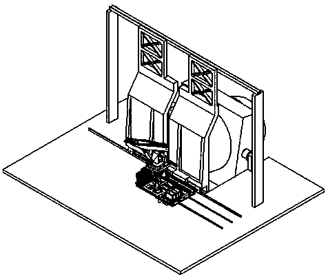
[0044] An automatic temperature measurement and / or sampling method for molten steel in a steelmaking converter. The method uses an automatic temperature measurement and sampling system in front of a steelmaking converter for separate temperature measurement or sampling, or simultaneous temperature measurement and sampling.
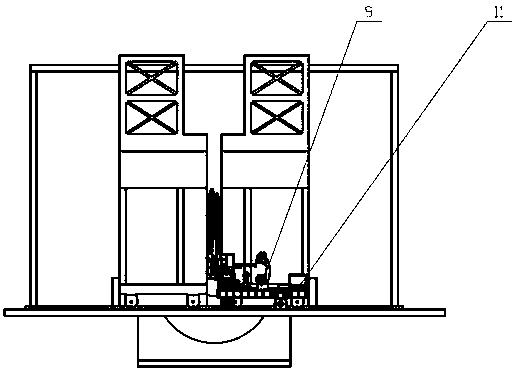
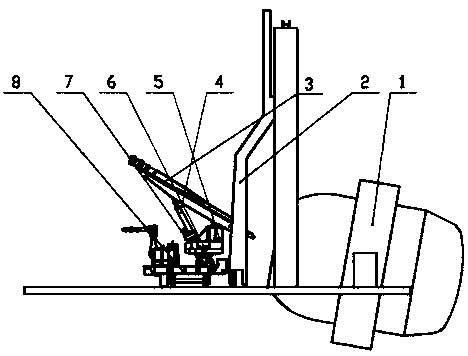
[0045] Such as Figure 1-7As shown, the automatic temperature measurement and sampling system in front of the steelmaking converter includes: an automatic temperature measurement and sampling part in front of the furnace, an automatic disassembly and assembly part of the casing, and a system electric control part.
[0046] The automatic temperature measurement and sampling part in front of the furnace is composed of a longitudinal moving device 3, an overturning device 4, an overturning safety device 5, a rotating device 6, a lateral moving device 7 and a walking trolley 8; the walking trolley 8 drives the entire system to follow the furnace The front fire...
PUM
 Abstract
Description
Claims
Application Information