Magnetic revolution counter and method for determining numbers of revolutions that can be determined by means of said revolution counter

A technology of magnetic rotation and number of rotations, which is applied in the field of automobile and transmission structure, and can solve problems affecting measurement results

Active Publication Date: 2018-08-03
LEIBNIZ INST FUR PHOTONISCHE TECHNOLOGIEN EV +1
View PDF8 Cites 5 Cited by
  • Summary
  • Abstract
  • Description
  • Claims
  • Application Information

AI Technical Summary

Problems solved by technology

In configurations with multiplexed voltage sources, not all Wheatstone half-bridges are at the same potential, so that in the case of measuring Wheatstone half-bridges, (here three-turn, or Wheatstone Stone half-bridges) parallel connection potential can influence the measurement results

Method used


Image

  • Magnetic revolution counter and method for determining numbers of revolutions that can be determined by means of said revolution counter
  • Magnetic revolution counter and method for determining numbers of revolutions that can be determined by means of said revolution counter
  • Magnetic revolution counter and method for determining numbers of revolutions that can be determined by means of said revolution counter

Examples


Embodiment Construction

[0064] An embodiment according to the invention of a revolution counter according to the invention with a 360° switch-on, which enables an integer number of revolutions per field angle, is described below with reference to any of the figures. One-to-one read.

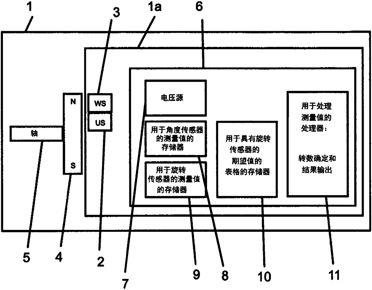
[0065] first, figure 1 The important components of such a tachometer system 1 are shown with a tachometer 1a according to the invention and a magnet system 4 with a north pole (N) and a south pole (S), the magnet system Installed on the rotating shaft 5. The tachometer 1 a consists of the following main components: rotation sensor US 2 , 360° angle sensor WS 3 and electronics 6 . Sensors 2 and 3 are installed in a stationary manner and detect the angular position and the number of revolutions of the rotating magnetic field. The electronics 6 comprise a voltage source 7 for the sensors 2 and 3 and for processing the measured values, a memory 8 for the measured values ​​of the angle sensor 3, a memory 9 for the measur...


PUM


Abstract

The invention relates to a magnetic revolution counter and to a method for determining a specifiable quantity n of revolutions of an external magnetic field that are to be determined, said external magnetic field produced by a rotating element (4), or a quantity n of magnetic poles of a rotating pole wheel, which quantity of magnetic poles can be moved past, or a linear magnetic scale that can bemoved past, containing a revolution sensor (2), which contains magnetic domain-wall conducting tracks, which consist of open spirals or multiply wound loops closed in themselves, which are formed by aGMR layer stack or a soft magnetic layer having locally present TMR layer stacks and into which magnetic 180 degrees domain walls can be introduced and - by measurement of the electrical resistance of specifiable spiral sections or loop sections - can be located, wherein a single domain wall is introduced into the domain-wall conducting tracks or at least two magnetic domain walls are introducedinto the domain-wall conducting tracks in such a way that the at least two domain walls are brought into a defined distance of greater than 360 degrees from each other, with respect to the location change thereof from a first to a second position in the event of rotation of the external magnetic field by the angle of greater than 360 degrees, and are lastingly thus spaced apart from each other andwherein electrical contacts arranged in a defined manner are provided on the domain-wall conducting tracks, which electrical contacts, together with associated domain-wall conducting track sections covered thereby, are interconnected to form separate but jointly readable Wheatstone half-bridges, wherein the resistance ratios determined by the Wheatstone half-bridges are stored as a signal level completely in a memory (9) as a table, which memory can be continuously compared with table-like target value patterns stored in a further memory (10) for each permissible revolution i (0 < i < n) in order to determine the number of revolutions and, for the number of revolutions i to be determined, the number of revolutions for which the measured resistance ratios match the target value pattern inthe memory (10) is output, determined by a corresponding processing unit (11).

Description

technical field [0001] The invention relates to a magnetic tachometer, which can be used in various technical fields, and to a method for determining the number of revolutions of an external magnetic field which can be ascertained by means of the tachometer. It is particularly advantageous for use in motor vehicle and transmission constructions, since the tachometer can be designed to be compact and can be operated without current. Background technique [0002] In principle, tachometers for contactless and powerless counting of rotations using magnetic domain walls (DW) are known per se, and are described, for example, in DE 10 2008 063 226 A1, DE 10 2010 022 611 A1 , DE 10 2011 075 306 A1 and DE 10 2013 018 680 A1 are described in detail. [0003] The revolution counters disclosed in the above-mentioned documents have in common that: [0004] The sensor system used consists of at least one sensor element and at least one external magnetic field, wherein either the sensor ...

Claims


Application Information

Patent Timeline
Patent Type & Authority Applications(China)
IPC IPC(8): G01D5/14G01P3/487G01D5/244G01R33/09
CPCG01D5/145G01D5/24476G01D5/2449G01P3/487G01R33/093G01B7/30
Inventor R·马泰斯M·迪格尔
Owner LEIBNIZ INST FUR PHOTONISCHE TECHNOLOGIEN EV
Why Eureka
Try Eureka