Roof rainwater collection utilization system

A rainwater collection and rainwater technology, which is applied in roof drainage, general water supply saving, roofing, etc., can solve the problems of excessive equipment, waste of cooling energy, and high roof temperature, and achieve the effects of overcoming long process, saving cooling energy, and reducing roof temperature

Pending Publication Date: 2018-08-07
深圳市奥亚生态科技有限公司
View PDF0 Cites 0 Cited by
  • Summary
  • Abstract
  • Description
  • Claims
  • Application Information

AI Technical Summary

Problems solved by technology

In order to facilitate operation and management, the system is generally installed in the basement, which occupies a large area, large volume, long process, and many equipments. Therefore, many green buildings can only change the functional layout of the basement. Under the current high construction cost, occupying the basement It will also lead to a decrease in space utilization, especially for high-rise or super high-rise buildings, the construction cost of the underground reservoir is very high, and the precious parking lot resources are wasted
At present, for the roof, there is still a problem that the roof temperature is too high in summer, resulting in high indoor temperature and wasting cooling energy.

Method used


Image

  • Roof rainwater collection utilization system
  • Roof rainwater collection utilization system
  • Roof rainwater collection utilization system

Examples


Embodiment Construction

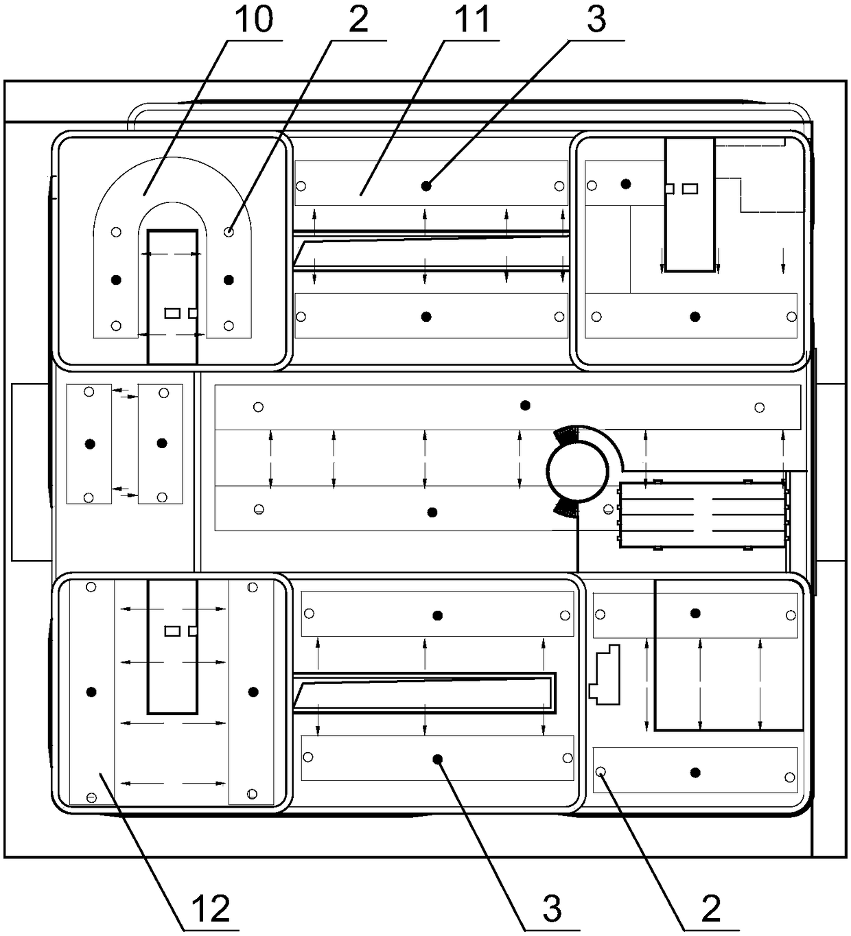
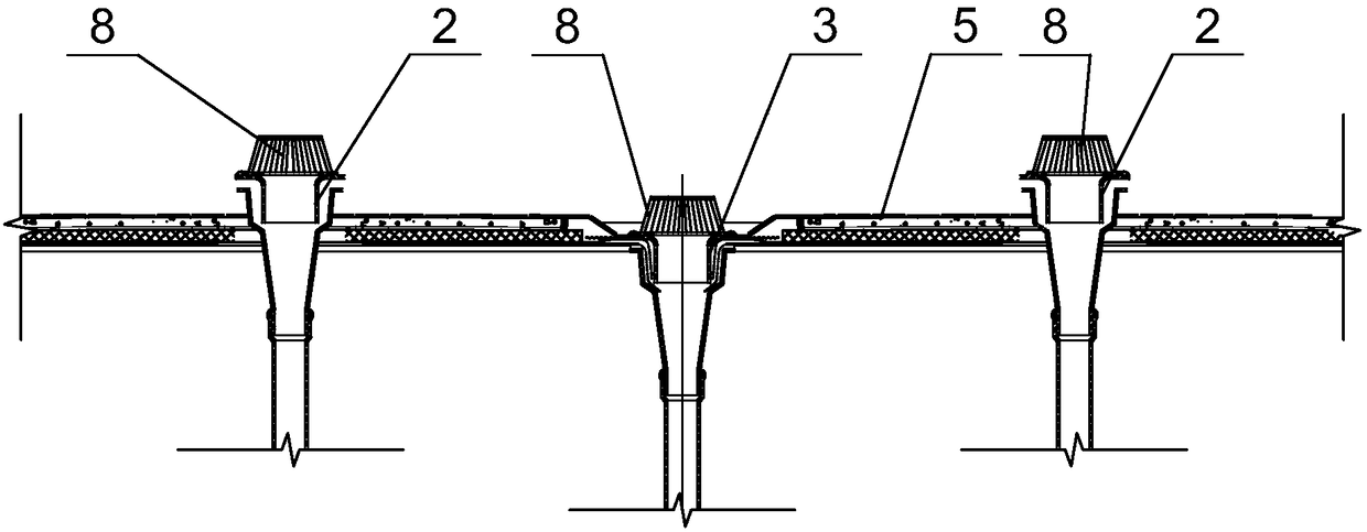
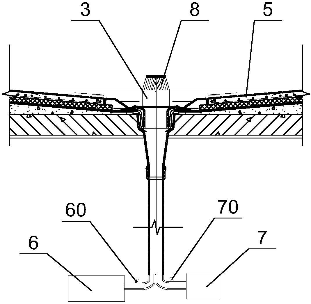
[0016] Such as Figure 1 ~ Figure 3 As shown, in the roof rainwater collection and utilization system of the embodiment of the present invention, the roof is the roof of a high-rise building, and the roof is provided with several reservoirs 10, 11, 12, ..., which can be used according to the roof of the building. The layout is set flexibly. There are pedestrian passages between the reservoirs. Each reservoir 10, 11, 12, ... is provided with a number of common rainwater pipes 2 and a pressure-bearing rainwater pipe. 3. The tops of the common rain downpipe 2 and the pressure-bearing rain downpipe 3 are equipped with a protective filter cover 8 for filtering impurities of larger particles and avoiding clogging. The water outlet is higher than the bottom surface 5 of the storage tank and leads to the outdoor rainwater pipe network 6, so that the accumulated rainwater overflows and discharges to the outdoor rainwater pipe network 6. The size of the bottom surface 5 of the pool is ...


PUM


Abstract

The invention discloses a roof rainwater collection utilization system. At least one reservoir is arranged on a roof and is internally provided with ordinary rainwater down pipes (2) and an artesian rainwater down pipe (3); water inlets of the ordinary rainwater down pipes (2) are higher than the bottom surface (5) of the reservoir and is led into an outdoor rainwater pipe network (6); a water inlet of the artesian rainwater down pipe (3) is flush to the bottom surface (5) of the reservoir, extends to the ground along an outer wall and is divided into two paths to be connected to the outdoor rainwater pipe network (6) and a rainwater secondary utilization pipe network (7) respectively; a first switch valve (60) is connected to a pipeline before the outdoor rainwater pipe network (6); and asecond switch valve (70) is connected to a pipeline before the rainwater secondary utilization pipe network (7). By adopting the roof rainwater collection utilization system provided by the invention, through on-off control of the first switch valve (60) and the second switch valve (70), the reservoir can be used for storing rainwater and automatically overflowing; when the rainfall is too largeor the reservoir needs to be emptied and maintained, the stored rainwater is drained to the outdoor rainwater pipe network (6); and when needing to be utilized, the stored rainwater is utilized through the rainwater secondary utilization pipe network (7). The roof rainwater collection utilization system can be widely applied to the building field.

Description

technical field [0001] The invention relates to a roof rainwater collection and utilization system. Background technique [0002] my country is a country with relatively poor water resources, and more than half of the cities are seriously short of water. Broadening sources of income and reducing expenditure are effective ways to alleviate the urban water shortage crisis. As a natural resource, rainwater recycling can not only relieve the pressure on the municipal rainwater pipe network, but also alleviate urban flood disasters. In green buildings, rainwater recycling is a key water-saving technical measure, such as eliminating the use of municipal water for landscape water bodies, and reducing the use of municipal water for non-potable water such as greening watering and square road washing. In the design of green buildings, the treated rainwater is mainly used for greening and sprinkling, landscape water replenishment and road square washing. The process is generally: out...

Claims


Application Information

Patent Timeline
Patent Type & Authority Applications(China)
IPC IPC(8): E03B1/00E04D13/00E03B3/02E04D13/08
CPCY02A20/108E03B1/00E03B3/02E03B2001/047E04D13/00E04D13/08E04D2013/0873
Inventor 杨奇飞项军
Owner 深圳市奥亚生态科技有限公司
Why Eureka
Try Eureka