
Radar clutter inhibition filter FIR design method

A filter design and clutter suppression technology, applied to instruments, radio wave measurement systems, etc., to achieve high computing performance, optimized performance, and flexible methods

Active Publication Date: 2018-08-07
LINGBAYI ELECTRONICS GRP
View PDF6 Cites 0 Cited by
  • Summary
  • Abstract
  • Description
  • Claims
  • Application Information

AI Technical Summary

Problems solved by technology

[0005] The present invention aims at the problem that the existing filter design technology in radar signal processing cannot meet more and more stringent application requirements, based on the optimal filtering theory and using MATLAB with powerful numerical calculation functions as the calculation software, it provides a specific A FIR filter coefficient generation method with optimal performance, adjustable parameters, flexible and practical, and high precision under radar application conditions

Method used


Image

  • Radar clutter inhibition filter FIR design method
  • Radar clutter inhibition filter FIR design method

Examples


Embodiment

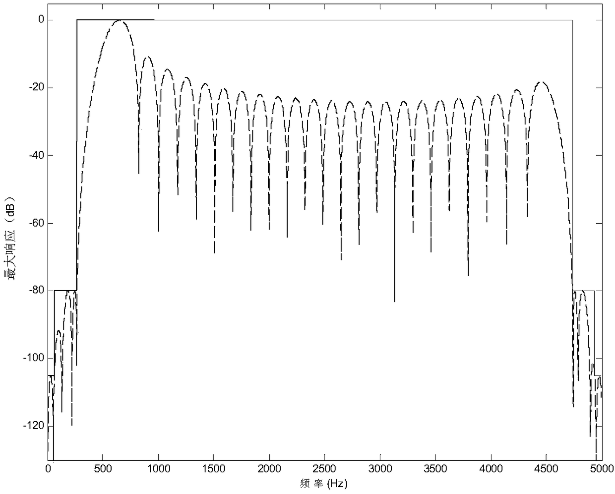
[0034] This embodiment takes the design of an FIR filter that takes into account both strong static ground clutter and strong cloud and rain clutter as an example, and uses MATLAB-R2010b software to specifically set forth the content of the invention of the present invention. In order to describe the content of the present invention for convenience, at first the following Definition of technical terms: The specific parameters of the radar system are: coherent pulse interval CPI containing N=32 pulses, f r =5kHz, the X-band wavelength is 3cm, assuming that the first stop band is the ground clutter suppression interval of ±1m / s, the intensity is 105dB, the second stop band cloud and rain clutter suppression interval is ±4m / s, the intensity is 80dB, and the rest is the passband, M=24 channels of the in-band coverage filter bank. According to the above parameters, its ideal filter frequency characteristic |H ideal (f)|if figure 2 Shown by the black solid line. The frequency re...


PUM


Abstract

The invention discloses a radar clutter inhibition filter FIR design method, and aims to provide a parameter adjustable and flexible and practical FIR filter coefficient forming method; the method comprises the following steps: using MATLAB software to design a FIR filter coefficient that suits a radar signal processing board; in a FIR filter coefficient forming process, setting radar system parameters and clutter parameters as variables with adjustable values, and building a normalization ideal FIR filter set frequency characteristics according to the radar system parameters and application environment demands; using the frequency characteristics to build a clutter covariance matrix; using the optimum filtering theory to calculate the FIR filter coefficient of each channel; finally, iterating and optimizing the FIR filter coefficient so as to reach the ideal FIR filter frequency characteristics, and maximizing an output signal to noise ratio. The method can greatly improve the radar clutter inhibition capability, is flexible, high in precision, and can be applied to special radar systems and special usage environments.

Description

technical field [0001] The invention relates to a radar clutter suppression FIR filter design method used in the field of radar signal processing. Background technique [0002] FIR is the abbreviation of Finite Impulse Response. FIR filter is the most basic component in digital signal processing system. It can guarantee arbitrary amplitude-frequency characteristics while having strict linear phase-frequency characteristics. At the same time, its unit sampling response is finite, so the filter is a stable system. FIR filters are widely used in communication, image processing, pattern recognition, radar signal processing and other fields. [0003] In a complex environment, the strong clutter formed by the reflection of ground objects, clouds, rain, sea waves, etc. seriously affects the detection of radar targets, especially the detection of slow and weak targets. In order to suppress strong ground clutter as much as possible, and at the same time carry out coherent accumulat...

Claims


Application Information

Patent Timeline
IPC IPC(8): G01S7/41
CPCG01S7/414
Inventor 狄中泉帅晓飞柏明法朱玉军刘华林李佩针刘敏
Owner LINGBAYI ELECTRONICS GRP
Learn More