RS485-based remote LED control system

A RS485, control system technology, applied in the field of lighting, can solve the problems of LED control without corresponding improvement and protection, unsuitable for long-distance control, and inability to realize remote transmission, etc., to save internal space and simple structure , Strong anti-interference effect

Inactive Publication Date: 2018-08-07
江苏楚门机器人科技有限公司
View PDF6 Cites 0 Cited by
  • Summary
  • Abstract
  • Description
  • Claims
  • Application Information

AI Technical Summary

Problems solved by technology

[0003] At present, for LED control, a dedicated light source controller is generally placed in the electrical cabinet to directly supply power and control the LED light array in the remote device. Due to the setting of the light source controller, the internal space of the electrical cabinet is greatly occupied. At the same time, because the power line will be included between the remote device and the electrical cabinet, the installation operation will be complicated, and the anti-interference performance will be crossed, so it is not suitable for industrial applications
At present, the LED control system disclosed in Chinese patent CN201267031Y with a universal serial bus transmission interface mainly protects the LED control scheme based on USB. Although it can avoid the setting of the light source controller, it has the problem of short control distance , not suitable for long-distance control; the low-cost LED driver with an improved serial bus disclosed in Chinese patent CN104011783B mainly focuses on the improvement and realization of the LED controller, but no corresponding improvement is made on the control of the LED and protection; the serial bus-connected group LED landscape light control system disclosed in Chinese patent CN100559909C, although it is a protected LED control system, is limited to local control and cannot realize remote transmission, which limits its application range, needs improvement

Method used


Image

  • RS485-based remote LED control system

Examples


Embodiment Construction

[0013] The present invention will be further described below in conjunction with the accompanying drawings.

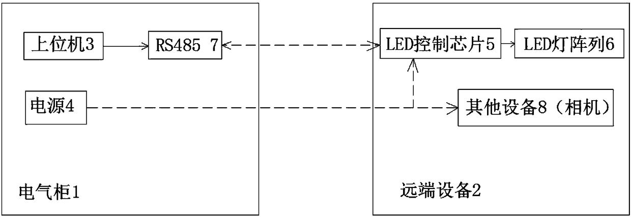
[0014] see as figure 1 As shown, the technical solution adopted in this specific embodiment is: it includes an electrical cabinet 1 and a remote device 2; wherein the electrical cabinet 1 is provided with a host computer 3, a power supply 4 and RS485 7; wherein the remote device 2 includes an LED control Chip 5 and LED light array 6; both ends of RS485 7 are connected to host computer 3 and LED control chip 5 respectively; said host computer 3 is connected to LED control chip 5 through RS485 7, and LED control chip 5 is connected to LED array 6 ; The power supply 4 is connected to the LED control chip 5 .

[0015] Further, the remote device 2 further includes other devices 8, and the power supply 4 is connected to the other devices 8; the other devices are cameras.

[0016] The working principle of this specific embodiment: through the software in the upper computer ...


PUM


Abstract

The invention, which relates to the field of lighting technology, provides an RS485-based remote LED control system comprising an electrical cabinet and a remote device. An upper computer, a power source and an RS485 are arranged in the electrical cabinet. The remote device consists of an LED control chip and an LED lamp array. The upper computer is connected with the LED control chip through theRS485; the LED control chip is connected to the LED array; and the power source is connected with the LED control chip. With removing of the light source controller, the cost and internal space of theelectrical cabinet are saved effectively; because of software controlling, the brightness and stroboscopic effect of the LED lighting in the remote device are controlled flexibly; the system has theexcellent anti-interference performance and is suitable for the industrial occasion; the use number of cables is reduced; and the system having high practicability is installed conveniently.

Description

technical field [0001] The invention relates to the technical field of lighting, in particular to an RS485-based remote LED control system. Background technique [0002] LED is a semiconductor component. At the beginning, it was mostly used as indicator lights, display light-emitting diode boards, etc.; with the emergence of white LEDs, it was also used as lighting. LED is called the fourth-generation lighting source or green light source. It has the characteristics of energy saving, environmental protection, long life, and small size. It is widely used in various indications, displays, decorations, backlights, general lighting, and urban night scenes. According to different functions, it can be divided into five categories: information display, signal lights, vehicle lamps, LCD backlight, and general lighting. [0003] At present, for LED control, a dedicated light source controller is generally placed in the electrical cabinet to directly supply power and control the LED...

Claims


Application Information

Patent Timeline
Patent Type & Authority Applications(China)
IPC IPC(8): H05B33/08H05B44/00
CPCH05B45/00
Inventor 裴磊吴红兵
Owner 江苏楚门机器人科技有限公司
Why Eureka
Try Eureka