Wire-feeding 3D printer with laser serving as heat source and printing method of wire-feeding 3D printer

A 3D printer and laser technology, applied in the field of 3D printing, can solve the problems of high printing cost, difficult equipment manufacturing, poor surface molding quality, etc., and achieve the effect of low printing cost, uniform and reliable temperature, and low manufacturing difficulty

Pending Publication Date: 2018-08-10
SHANGHAI IND TECH INST
View PDF18 Cites 7 Cited by
  • Summary
  • Abstract
  • Description
  • Claims
  • Application Information

AI Technical Summary

Problems solved by technology

[0005] In view of the shortcomings of the prior art described above, the purpose of the present invention is to provide a wire-feeding 3D printer with laser as a heat source and its printing method, which is used to solve the problem of using electron beam fuse additives for 3D printing in the prior art. , there are problems of high difficulty in equipment manufacturing and high printing costs, and the problem of poor surface molding quality when using arc additive materials for 3D printing

Method used


Image

  • Wire-feeding 3D printer with laser serving as heat source and printing method of wire-feeding 3D printer
  • Wire-feeding 3D printer with laser serving as heat source and printing method of wire-feeding 3D printer
  • Wire-feeding 3D printer with laser serving as heat source and printing method of wire-feeding 3D printer

Examples


Embodiment Construction

[0111] The implementation of the present invention will be illustrated by specific specific examples below, and those skilled in the art can easily understand other advantages and effects of the present invention from the contents disclosed in this specification.

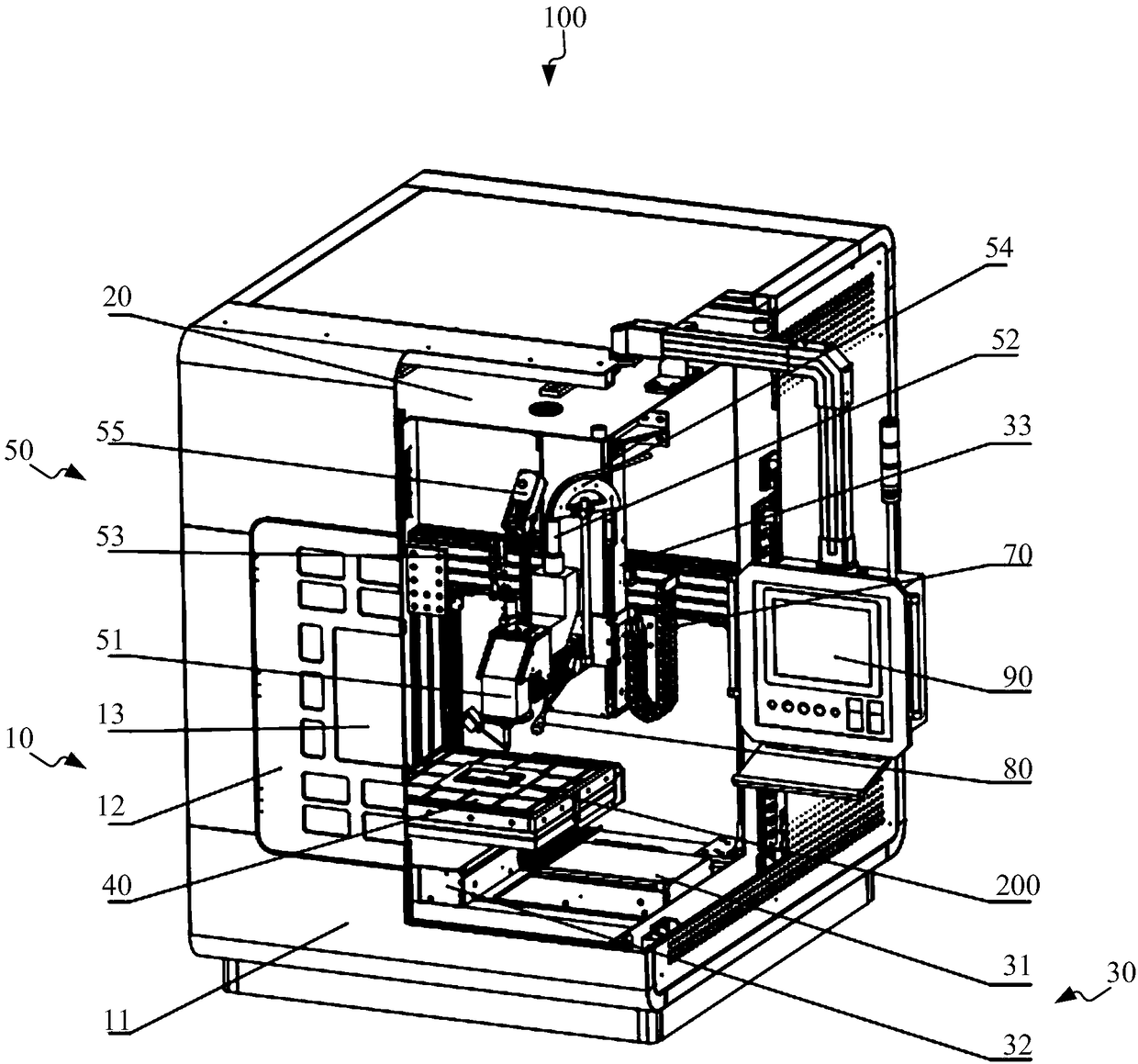
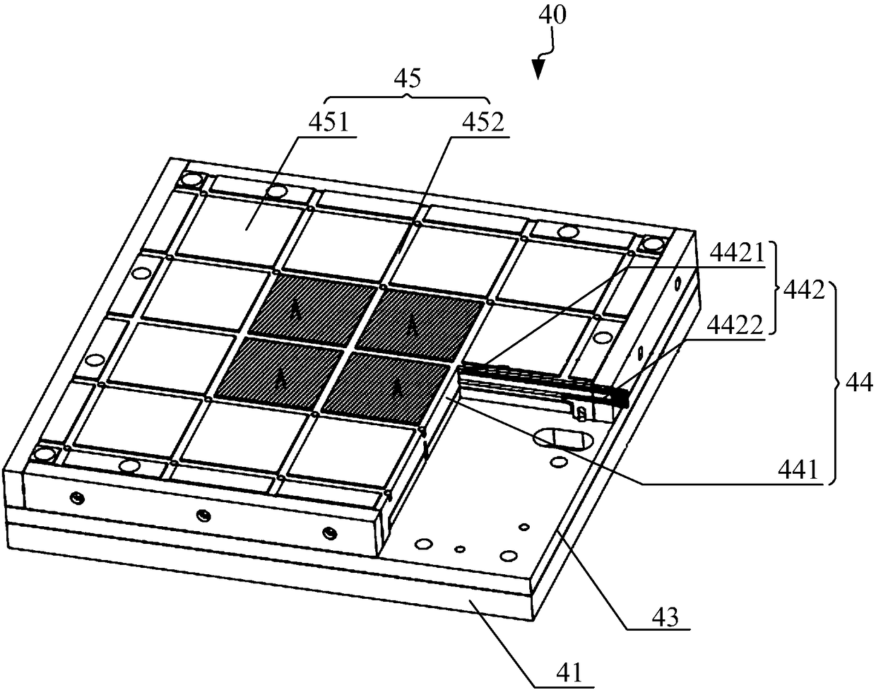
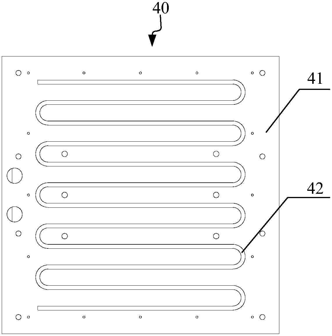
[0112] see Figure 1 to Figure 6 . It should be noted that the structures, proportions, sizes, etc. shown in the drawings attached to this specification are only used to match the content disclosed in the specification, for those who are familiar with this technology to understand and read, and are not used to limit the implementation of the present invention. Limiting conditions, so there is no technical substantive meaning, any modification of structure, change of proportional relationship or adjustment of size, without affecting the effect and purpose of the present invention, should still fall within the scope of the present invention. The disclosed technical content must be within the scope covered. At the sa...


PUM


Abstract

The invention provides a wire-feeding 3D printer with laser serving as a heat source and a printing method of the wire-feeding 3D printer. The 3D printer comprises a housing, a three-axis movement machine tool, a working table and a laser wire-feeding device, wherein a sealed cavity is disposed in the housing; the three-axis movement machine tool is mounted in the sealed cavity and comprises an X-axis movement module, a Y-axis movement module and a Z-axis movement module; the working table is mounted on the movement modules of the three-axis movement machine tool and used for driving a printing substrate mounted on the working table to move along the X-axis movement module, the Y-axis movement module and the Z-axis movement module; and the laser wire-feeding device is mounted above the working table and used for coaxially transmitting laser and metal wires towards the preset forming position of the focusing spot identification in the printing substrate. By means of the wire-feeding 3Dprinter with laser serving as the heat source and the printing method of the wire-feeding 3D printer, the problems that the equipment manufacturing difficulty is high and the printing cost is high when existing 3D printing is performed through an electron beam fuse wire additive method are solved and the problem that the surface forming quality is poor when 3D printing is performed through an electric arc additive method is also solved.

Description

technical field [0001] The invention relates to the field of 3D printing, in particular to a wire-feeding 3D printer using laser as a heat source and a printing method thereof. Background technique [0002] The commonly used forms of metal additive 3D printing are divided into metal wire feeding printing and metal powder additive printing according to different raw materials; and metal powder additive 3D printers are due to low material utilization, poor stability of powder feeding, and two melting channels. The powder in the semi-molten state is easy to adhere to the surface of the molded part, and the printing effect is poor in some large parts such as thin-walled parts; for the additive manufacturing of such parts, metal wire feeding 3D is generally used. Printing method, and this printing method has many advantages, such as higher feeding accuracy, easier control, high material utilization rate, low cost, etc., so it has a broader development space. [0003] The existin...

Claims


Application Information

Patent Timeline
Patent Type & Authority Applications(China)
IPC IPC(8): B22F3/105C23C24/10B33Y30/00B33Y10/00
CPCC23C24/10B33Y10/00B33Y30/00B22F10/00B22F10/77B22F12/70B22F12/53B22F12/33B22F12/20B22F12/90B22F12/44B22F10/32B22F10/25B22F12/17B22F12/46Y02P10/25
Inventor 周伟民闵国全司君平徐栋吴杰华
Owner SHANGHAI IND TECH INST
Why Eureka
Try Eureka