Tool for repairing and grinding center holes of output shaft of aero-engine and repairing and grinding work method of tool

A technology of engine output and aero-engine, which is applied in the direction of manufacturing tools, metal processing equipment, and other manufacturing equipment/tools, etc., to achieve the effects of shortening the required time, ensuring the quality of repair and research, and the effect of simple and reliable repair and research work methods

Pending Publication Date: 2018-08-10
CHINA HANGFA CHANGZHOU LANXIANG MACHINERY CO LTD
View PDF10 Cites 5 Cited by
  • Summary
  • Abstract
  • Description
  • Claims
  • Application Information

AI Technical Summary

Problems solved by technology

[0005] The technical problem to be solved by the present invention is a tool for repairing and researching the center hole of the output shaft of an aero-engine and its repairing working method. The tooling structure of the present invention is simple and easy to process. It eliminates the manual scraping and repairing of the prior art, eliminates the instability of manual repairing, and can effectively avoid the phenomenon that the output shaft is damaged by the hand scraper in the process of manual repairing. The working method of the present invention is simple and reliable , under the premise of ensuring the quality of training and research, the time required for training and research has been greatly shortened

Method used


Image

  • Tool for repairing and grinding center holes of output shaft of aero-engine and repairing and grinding work method of tool
  • Tool for repairing and grinding center holes of output shaft of aero-engine and repairing and grinding work method of tool
  • Tool for repairing and grinding center holes of output shaft of aero-engine and repairing and grinding work method of tool

Examples


Embodiment 2

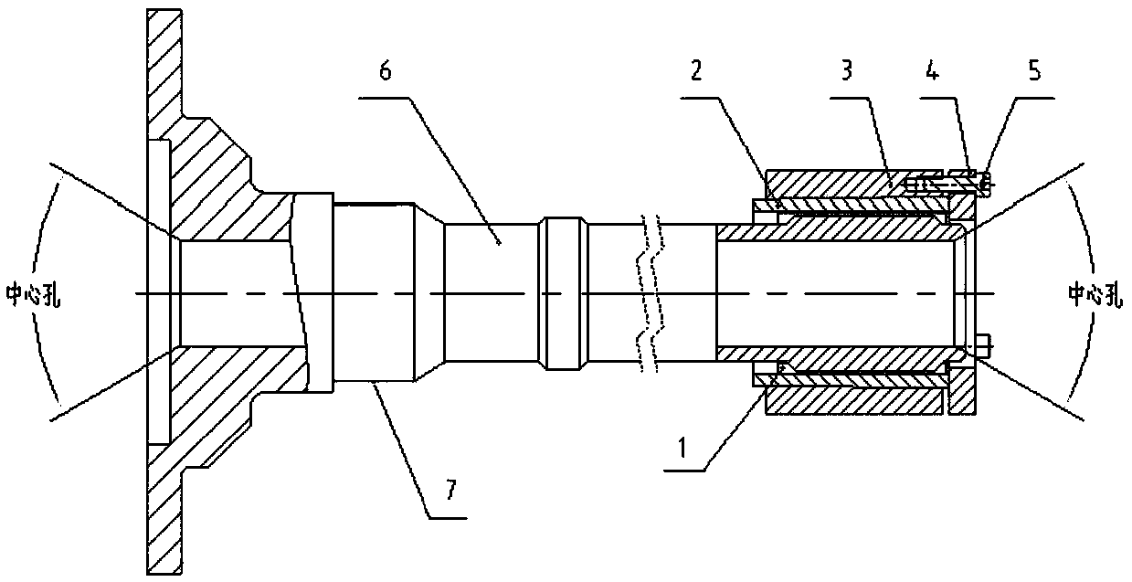
[0031] The method for repairing and researching the center hole of the output shaft of the aeroengine described in the first embodiment includes a method for repairing the left center hole of the engine output shaft 6 and a method for repairing the right center hole.

[0032] The method for repairing the left central hole of the engine output shaft 6: first install the tooling of the present invention on the spline groove at the right end of the engine output shaft 6, place the outer circular surface 7 of the engine output shaft 6 on a lathe Supported on the central center frame, the outer circular surface of the outer taper sleeve 3 is clamped on the lathe chuck, the lathe is turned on and the outer circular surface of the outer taper sleeve 3 is dialed with a dial indicator to find alignment, and the outer circular surface of the outer tapered sleeve 3 is aligned with a turning tool The left center hole of the output shaft 6 of the engine is turned and repaired, and the surfa...


PUM


Abstract

The invention relates to a tool for repairing and grinding center holes of an output shaft of an aero-engine and a repairing and grinding work method of the tool. The tool comprises rolling rods, aninner taper sleeve, an outer taper sleeve, a pressing plate and a screw, wherein the rolling rods are arranged and placed in a spline groove of the output shaft at equal intervals in a circumferentialmode, an inner hole of the inner taper sleeve is in contact compression with the rolling rods, and the inner conical surface of the outer taper sleeve is compressed with the outer conical surface ofthe inner taper sleeve in a cooperating mode; and the left end face of the pressing plate is in contact compression with the right end face of the inner taper sleeve, the screw penetrates through a through hole in the pressing plate and is in threaded connection with a threaded hole in the end face of the inner taper sleeve. The tool is simple in structure and easy to machine; according to the repairing and grinding work method of the tool, manual hand scraping repairing and grinding in the prior art is replaced by machining repairing and grinding, so that instability of manual repairing and grinding is eliminated, and the phenomenon that the output shaft is damaged by a hand scraper in the manual repairing and grinding process can be effectively avoided; and the repairing and grinding working method of the tool is simple, convenient and reliable, and on the premise of guaranteeing the repairing and grinding quality, the time required for repairing and grinding is shortened.

Description

technical field [0001] The invention relates to a tooling for repairing and researching, in particular to a tooling for repairing and researching a center hole of an output shaft of an aeroengine and a repairing and researching working method thereof. Background technique [0002] The engine output shaft is the power output device of the engine, which has the characteristics of high precision requirements, high surface quality requirements, and consistent wall thickness. In order to ensure the above quality requirements, the processing technology of the output shaft needs to be processed by double-top clamping method , the above-mentioned double-top clamping method requires pre-machining a center hole at both ends of the output shaft. The center hole is the process hole processed to determine the center of the workpiece. The center hole is used as the positioning reference of the workpiece and bears the weight and cutting force of the workpiece. , so the processing quality o...

Claims


Application Information

Patent Timeline
Patent Type & Authority Applications(China)
IPC IPC(8): B23P23/04B24B5/36
CPCB23P23/04B24B5/36
Inventor 张明艳韩志杨凌斐蔡立猛
Owner CHINA HANGFA CHANGZHOU LANXIANG MACHINERY CO LTD
Why Eureka
Try Eureka