
Large-scale biomass and waste pyrolysis furnace

A biomass and pyrolysis furnace technology, used in coke ovens, indirect heating dry distillation, special forms of dry distillation, etc., can solve the problems that the pyrolyzer cannot be self-heating, hinder heat transfer, etc., and achieves expanded adaptability, less heat, The effect of a large heating area

Active Publication Date: 2020-10-02
TONGJI UNIV
View PDF18 Cites 0 Cited by
  • Summary
  • Abstract
  • Description
  • Claims
  • Application Information

AI Technical Summary

Problems solved by technology

However, for biomass and waste with high moisture content or high viscosity, the material may stick to the heating surface, hindering heat transfer; the pyrolyzer cannot be self-heating, so biomass with high humidity or high viscosity Or waste materials can only rely on the heating surface to transfer heat. When the heat transfer is blocked, the blanking auxiliary mechanism may also be stuck and unable to operate. Therefore, this pyrolyzer is only suitable for materials with a moisture content of 35% and below.

Method used


Image

  • Large-scale biomass and waste pyrolysis furnace
  • Large-scale biomass and waste pyrolysis furnace
  • Large-scale biomass and waste pyrolysis furnace

Examples


Embodiment 1

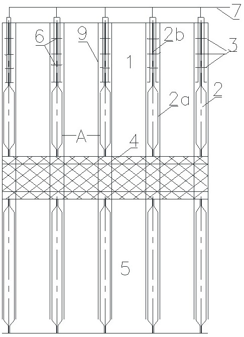
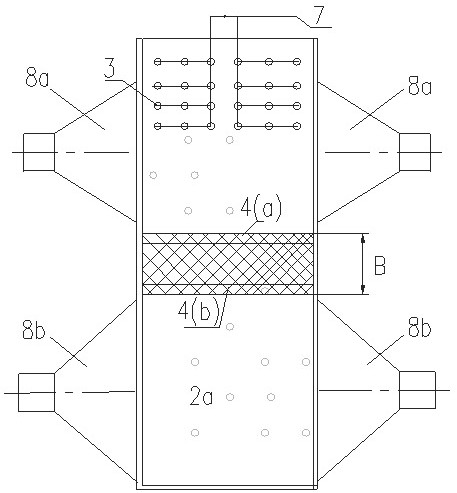
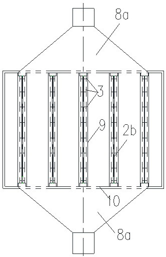
[0060] figure 1 Shows an implementation of a large biomass and waste pyrolysis furnace cavity provided by the present invention, figure 2 The relationship between the layout of the air flow and the position of the heating surface is shown. image 3 with Figure 4 The top view is used to further explain the relationship between the arrangement of the air flow in the preheating zone and the pyrolysis zone and the position of the heating surface. The large-scale pyrolysis furnace of this specific embodiment includes a preheating section nozzle area 1; a heating chamber 2 and heating surfaces 2a on both sides thereof; a nozzle group 3 and a pipe 7 for feeding hot air; the interface between the preheating area and the pyrolysis area 4 is composed of biomass and waste materials; the upper part is the preheating zone temperature control interface 4a; the lower part is the pyrolysis zone temperature control interface 4b; the pyrolysis zone 5; the nozzle holder 6 in the preheating zone...

Embodiment 2

[0065] For a certain batch of sludge treatment tasks of 105 tons / day, after drying, the moisture content is still as high as 45%. The large-scale pyrolysis furnace adopts the pyrolysis ( figure 1 ), the sludge is fed to the preheating section 1 by the cooperation of the uniform blanking mechanism and the heating surface cleaning mechanism 9 configured in the system; the generated water vapor is guided and discharged by the water vapor outlet area 8a, according to formulas (1) and (2) ) Controlling the hot flue gas flow rate of 350°C from the nozzle 3 and the pumping volume of the water vapor outlet area 8a, so that the temperature at the temperature control interface 4a of the preheating zone is controlled at about 95°C. There is a distance A between the heating surface at the lower edge of the water vapor outlet area 8a away from 4a. The preheated and dried material descends to the pyrolysis zone 5. The heating chamber inside the heating surface 2a of the pyrolysis zone is fe...

Embodiment 3

[0067] A certain batch of reed straw harvested in summer has a moisture content of up to 52%, a processing capacity of 100 tons / day, and a maximum particle size of 30 mm after crushing. The large pyrolysis furnace of the present invention is used for pyrolysis ( figure 1 ), the broken reed straw is fed to the preheating section 1 by the cooperation of the uniform blanking mechanism (such as the uniform blanking mechanism disclosed in Chinese invention patent 201410412201.2) and the heating surface cleaning mechanism 9 configured in the system; the nozzle 3 sprays 380 The hot flue gas at ℃ directly heats the straw, and the generated water vapor is guided and discharged by the water vapor outlet area 8a. According to formulas (1) and (2), the flow rate of the hot flue gas ejected from the nozzle 3 and the exhaust volume of the outlet area 8a are controlled. The temperature at the temperature control interface 4a of the preheating zone is controlled at about 95°C. The distance bet...


PUM


Abstract

The invention relates to a large biomass and waste pyrolysis furnace, comprising a pyrolysis furnace cavity, a water vapor lead-out area, a volatile component lead-out area and a hot air pipeline. Thelarge biomass and waste pyrolysis furnace has the characteristics of compactness and self-heating. The pyrolysis furnace cavity is formed by vertically arranged heating cavities, and each heating cavity is divided into a preheating section spray nozzle area and a pyrolysis area from top to bottom; the two sides of each heating cavity are heating surfaces; the preheating section spray nozzle areasare positioned at a feeding end, the hot air flow sprayed out by spray nozzles is directly in contact with heated biomass or waste, and self-heating is formed by means of airflow guiding; the pyrolysis of the biomass or the waste is realized by means of the spray nozzles and the heating surfaces at the two sides of the heating cavities together; the evaporated water and the volatile component arelead out from the water vapor lead-out area and the volatile component lead-out area which are respectively arranged at the two sides of a vertical direction perpendicular to the heating surfaces. According to the large biomass and waste pyrolysis furnace, the distances between the heating surfaces can be flexibly set, for instance, the distance between the heating surfaces of the preheating areaand the distances between the heating surfaces of the pyrolysis area can be different from each other, so that the pyrolysis requirements of materials with different properties and shapes can be met.

Description

Technical field [0001] The invention belongs to the field of energy and waste innocuous and resource treatment technology, and specifically relates to a large-scale biomass and waste pyrolysis furnace, which has compactness and internal heat characteristics, can realize the pyrolysis of biomass or waste, and is convenient for its energy And resource. Background technique [0002] Pyrolysis is one of the important means of biomass or waste recycling. The important difference between pyrolysis and gasification and incineration is that the pyrolysis device is generally externally heated, that is, the pyrolysis process is completed by external heating ; The pyrolysis furnace for gasification and incineration is generally internally heated, that is, the material itself is heated by the heat of the material itself to complete the thermal conversion process. However, pyrolysis, gasification, and incineration processes are more environmentally friendly. Compared with gasification, pyrol...

Claims


Application Information

Patent Timeline
Patent Type & Authority Patents(China)
IPC IPC(8): C10B53/00C10B47/02C10B57/10
CPCC10B47/02C10B53/00C10B57/10
Inventor 戴晓虎陈德珍胡雨燕尹丽洁戴翎翎俞海淼
Owner TONGJI UNIV
Learn More