Piston ring clamp set for rapid clamping and thread locking prevention

A piston ring and jig assembly technology, applied in ion implantation plating, metal material coating process, coating, etc., can solve unrealistic problems, achieve the effects of improving production efficiency, convenient loading and unloading, and ensuring normal loading and unloading

Pending Publication Date: 2018-08-10
大连威钛克纳米科技有限公司
View PDF0 Cites 0 Cited by
  • Summary
  • Abstract
  • Description
  • Claims
  • Application Information

AI Technical Summary

Problems solved by technology

[0005] The surface of the piston ring needs to be coated, and it is very unrealistic to stack the piston ring directly in the vacuum chamber

Method used


Image

  • Piston ring clamp set for rapid clamping and thread locking prevention
  • Piston ring clamp set for rapid clamping and thread locking prevention
  • Piston ring clamp set for rapid clamping and thread locking prevention

Examples


Embodiment Construction

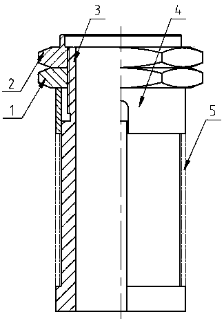
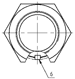
[0015] The structure of the piston ring fixture set for fast clamping and anti-locking of the thread of the present invention is as follows: figure 1 and figure 2 As shown, it includes a compression sleeve 4, a key 6, a compression nut 1, a lock nut 2, and a clamp sleeve 3. The outer circle of the clamp sleeve 3 is provided with a long strip key 6, and the width of the key 6 is the same as the diameter of the clamp sleeve 3. The sum of the sum is greater than the diameter of the ring mouth of the piston ring 5, the piston ring 5 is set on the clamp sleeve 3, the ring mouth of the piston ring 5 is positioned by the key 6, the clamp sleeve 3 is located on the upper part of the piston ring 5, and the compression sleeve 4 is set, and the clamp The upper part of the tool cover 3 is provided with an external thread, and the clamp cover 3 is located on the upper part of the compression sleeve 4 to install the compression nut 1 and the lock nut 2 in sequence, and the upper part of th...


PUM


Abstract

Provided is a piston ring clamp set for rapid clamping and thread locking prevention. The excircle of a clamp sleeve is provided with a long-strip-shaped spline, the sum of the width of the spline andthe diameter of the clamp sleeve is greater than the diameter of a gap of a piston ring, the clamp sleeve is sleeved with the piston ring, the gap of the piston ring is positioned through the spline,and the portion, located on the upper portion of the piston ring, of the clamp sleeve is sleeved with a compression sleeve; outer threads are arranged on the upper portion of the clamp sleeve, a compression nut and a locking nut are sequentially mounted on the portion, located on the upper portion of the compression sleeve, of the clamp sleeve, and a protruded metal ring is arranged on the upperportion of the locking nut. By the adoption of the piston ring clamp set for rapid clamping and the thread locking prevention, film coating requirements are met to the maximum degree, usage is convenient and flexible, and the production efficiency is greatly improved; a plurality of piston rings can be clamped one time and can sleeve a rotation shaft rod layer by layer, and because the piston rings are not directly placed on the rotation shaft piece by piece, it is very convenient to load and unload the piston rings; the piston ring clamp set is accurate in positioning and high in film coatingquality; due to the design of the locking nut, normal loading and unloading are effectively ensured after film coating, and the piston ring clamp set has a thread locking prevention function.

Description

technical field [0001] The invention relates to the field of coating equipment, in particular to a clamping equipment for piston ring coating. Background technique [0002] Common methods for preparing DLC ​​films include vacuum evaporation, sputtering, plasma-assisted chemical vapor deposition, and ion implantation. Among these methods, the traditional vacuum evaporation coating method has a high deposition rate and high purity of the formed film, but due to the low energy of the thermally evaporated atoms or molecules on the substrate, the surface mobility is very low, resulting in the combination of the film and the substrate. The poor intensity, coupled with the shadow effect of the deposited atoms on the atoms that fly later, greatly limits the application of vacuum evaporation coating technology. The ion implantation method can significantly change the friction coefficient, wear resistance, and corrosion resistance of the material, and there is no clear interface betw...

Claims


Application Information

Patent Timeline
Patent Type & Authority Applications(China)
IPC IPC(8): C23C14/50C23C14/04
CPCC23C14/50C23C14/04
Inventor 王岩刘洋
Owner 大连威钛克纳米科技有限公司
Why Eureka
Try Eureka