
Method for designing wind turbine blunt trailing edge oval wing section

A design method and blunt trailing edge technology, applied to wind turbines, wind turbines, mechanical equipment, etc. that are consistent with the wind direction, can solve the problems of high production cost, cambered airfoil, small stall angle of attack, etc., and achieve design The method is simple and easy to understand, the strength and stiffness are improved, and the effect of increasing the stall angle of attack

Active Publication Date: 2018-08-10
NORTHWESTERN POLYTECHNICAL UNIV
View PDF9 Cites 2 Cited by
  • Summary
  • Abstract
  • Description
  • Claims
  • Application Information

AI Technical Summary

Problems solved by technology

[0009] In order to overcome the disadvantages of cumbersome design methods in the prior art, generally small stall angle of attack, and most of the airfoils obtained have camber or negative loading, and require high precision, resulting in high final manufacturing costs, the present invention proposes a A Design Method for Elliptical Airfoil with Obtuse Trailing Edge of Wind Turbine

Method used


Image

  • Method for designing wind turbine blunt trailing edge oval wing section
  • Method for designing wind turbine blunt trailing edge oval wing section
  • Method for designing wind turbine blunt trailing edge oval wing section

Examples


Embodiment Construction

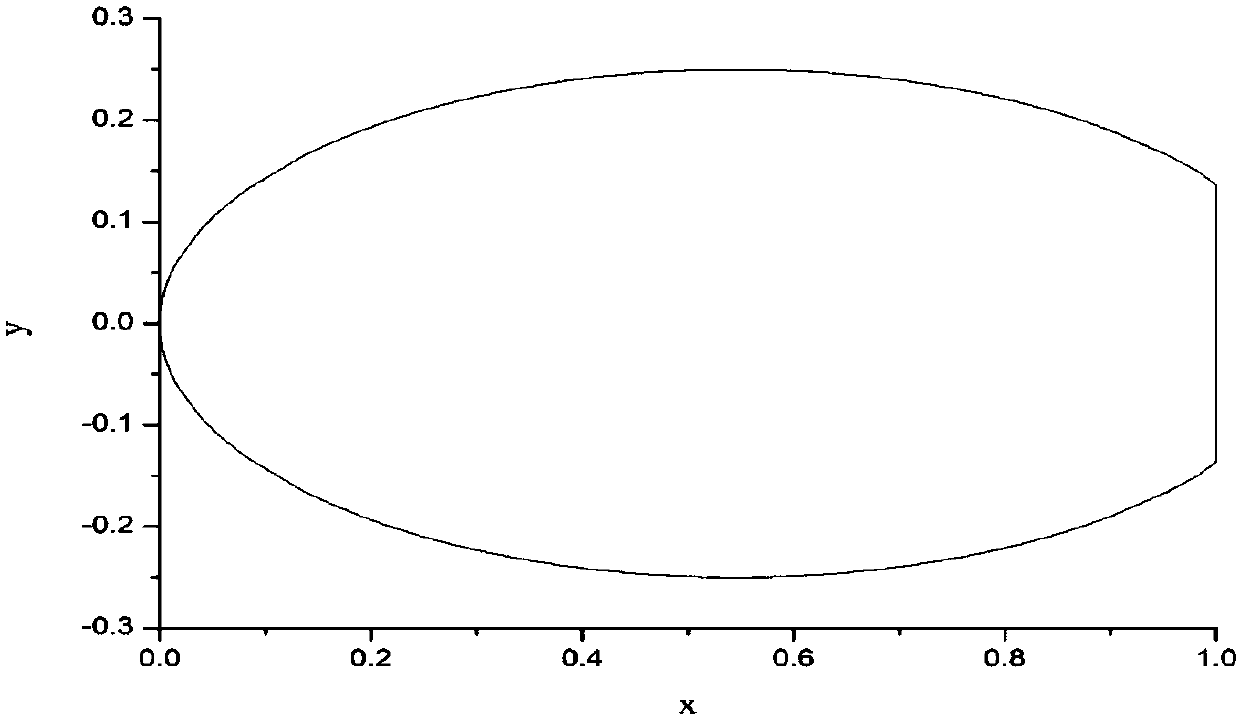
[0055] This embodiment is a design method for an elliptical airfoil with a blunt trailing edge of a high-performance wind turbine. It is based on an elliptical airfoil, and the trailing edge of the initial airfoil is cut off using the design method proposed in this embodiment.

[0056] Specific steps are as follows:

[0057] Step 1. Set the geometric parameters of the blunt trailing edge elliptical airfoil.

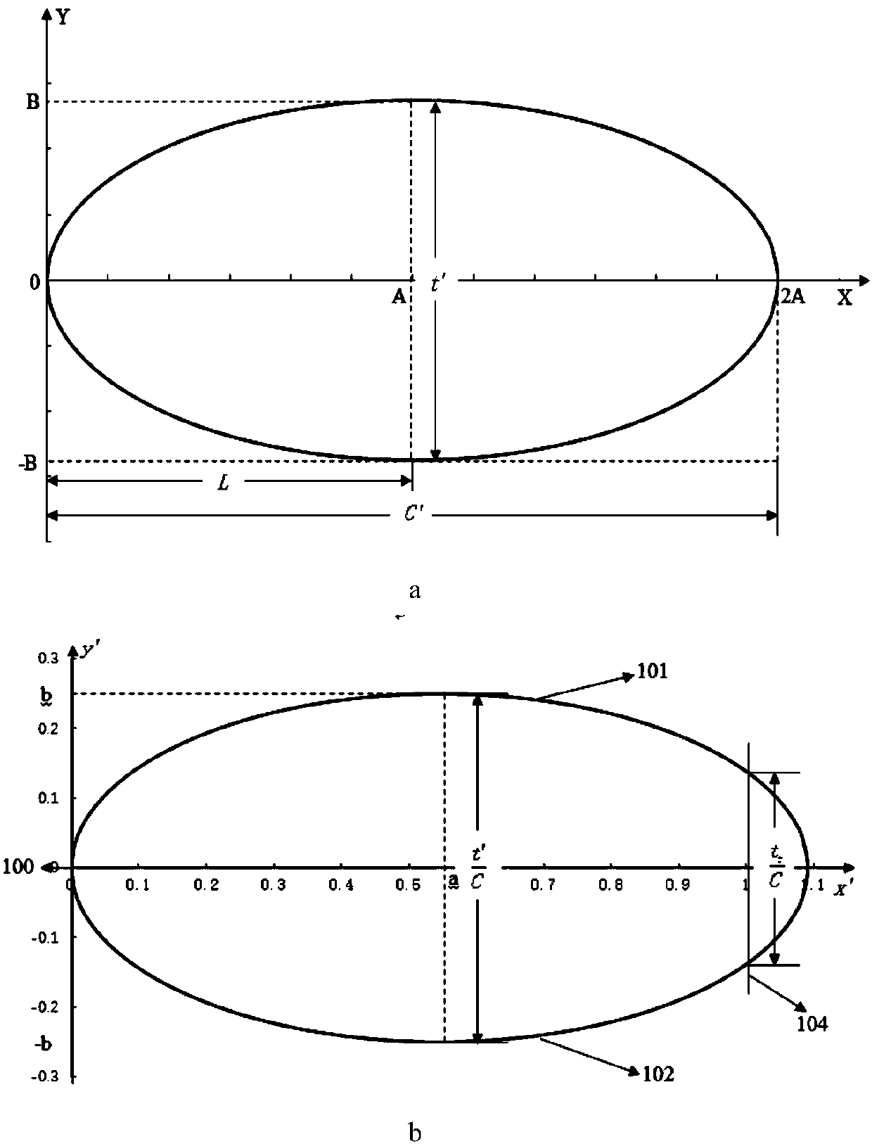
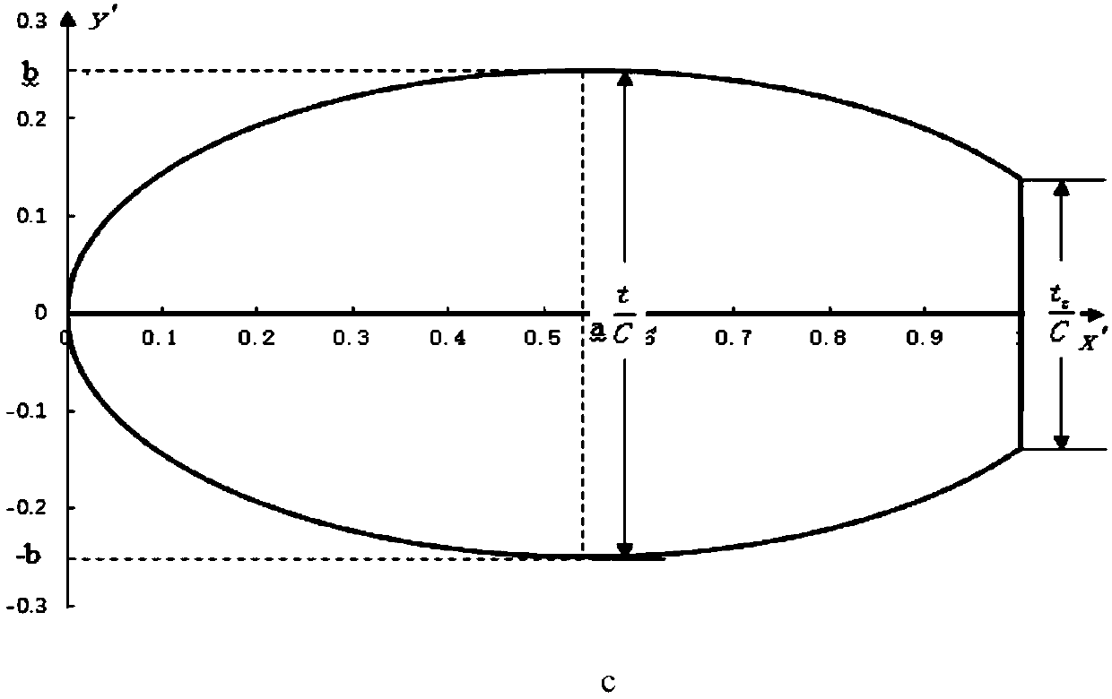
[0058] The geometric parameters of the blunt trailing edge elliptical airfoil include the relative thickness of the blunt trailing edge elliptical airfoil and the relative thickness of the trailing edge Said C is the chord length, which is the distance between the apex of the leading edge of the airfoil and the apex of the trailing edge of the airfoil, and the relative thickness refers to the ratio of the maximum thickness t between the upper and lower surfaces of the airfoil to the chord length C. Edge relative thickness refers to the thickness t at the trailing edge...


PUM


Abstract

Provided is a method for designing a wind turbine blunt trailing edge oval wing section. The semi-major axis, the semi-minor axis and the primary wing section rear trailing edge section of a primary wing section are determined through a dimensionless geometric equation of the primary wing section; the trailing edge of the primary wing section is cut off, and the trailing edge of the blunt trailingedge oval wing section is obtained; and the portion between the leading edge and the trailing edge section of the primary wing section is the blunt trailing edge oval wing section. According to the method, aiming at the defects of an existing large-thickness wind turbine wing section design method, the characteristic that the larger the relative thickness of the oval wing section is, the larger the stalling attack angle is and the advantages of a bunt trailing edge improving method are combined, the wing section cross sectional moment of inertia is 50% larger than the cross sectional moment of inertia of a large-thickness blunt trailing edge wind turbine wing section FX77 with the same chord length, the pressure gradient of the wing section suction surface rear section is 25% smaller thanthat of an FX77 suction surface rear section, the lift coefficient and stalling attack angle of the wing section are effectively increased, and the strength and rigidity of wind turbine blades are improved.

Description

technical field [0001] The invention relates to a wind turbine airfoil design method, in particular to a design method for an elliptical airfoil with a large thickness blunt trailing edge. Background technique [0002] Blade design is the core technology of wind turbine design. Blade performance determines wind energy utilization, load characteristics, noise level, etc. Among them, blade profile airfoil is the most important factor determining blade performance. Nowadays, due to the large-scale and regional development of wind turbines, the special airfoils for wind turbines with a relative thickness of more than 30% are commonly used in the middle and inner sides of the blade span. The blade weight and system loads are significant. [0003] In 2014, Qiao Baoying of the China Aerodynamic Research and Development Center published the "Research Review of Wind Turbine Airfoil Design" on the "Proceedings of the Ninth National Wind Energy Application Technology Annual Conference...

Claims


Application Information

Patent Timeline
IPC IPC(8): F03D1/06G06F17/50
CPCF03D1/0675G06F30/17G06F30/20Y02E10/72
Inventor 高永卫任玉洁师尧
Owner NORTHWESTERN POLYTECHNICAL UNIV
Learn More