Intelligent non-pulse grouting pump for indoor model test and using method of intelligent non-pulse grouting pump
An indoor model and test technology, applied in the direction of pumps, pump control, piston pumps, etc., can solve the problems of grouting pressure, grouting volume not clear, grouting pressure instability, difficult to meet indoor model tests, etc., to overcome The effect of grouting pressure instability
- Summary
- Abstract
- Description
- Claims
- Application Information
AI Technical Summary
Problems solved by technology
Method used
Image
Examples
Embodiment 1
[0058] The embodiment of the present invention provides an intelligent non-pulse grouting pump for indoor model testing and its use method. The PLC control system is used to transmit signals to control the activity of the propulsion cylinder, thereby adjusting the movement of the piston rod and changing the pumping system. The pressure in the cavity and the rodless cavity can achieve the same grouting speed, and can realize continuous grouting without pulse when the piston rod moves up and down.
[0059] An aspect of the embodiments of the present invention provides an intelligent non-pulse grouting pump for indoor model tests.
[0060] The structural diagram of an intelligent non-pulse grouting pump for indoor model tests provided by the embodiment of the present invention is as follows: figure 1 As shown, the device includes: pump body, piston rod, pumping system, slurry storage tank, slurry delivery pipe, slurry outlet pipe, propulsion cylinder, hydraulic system and PLC con...
Embodiment 2
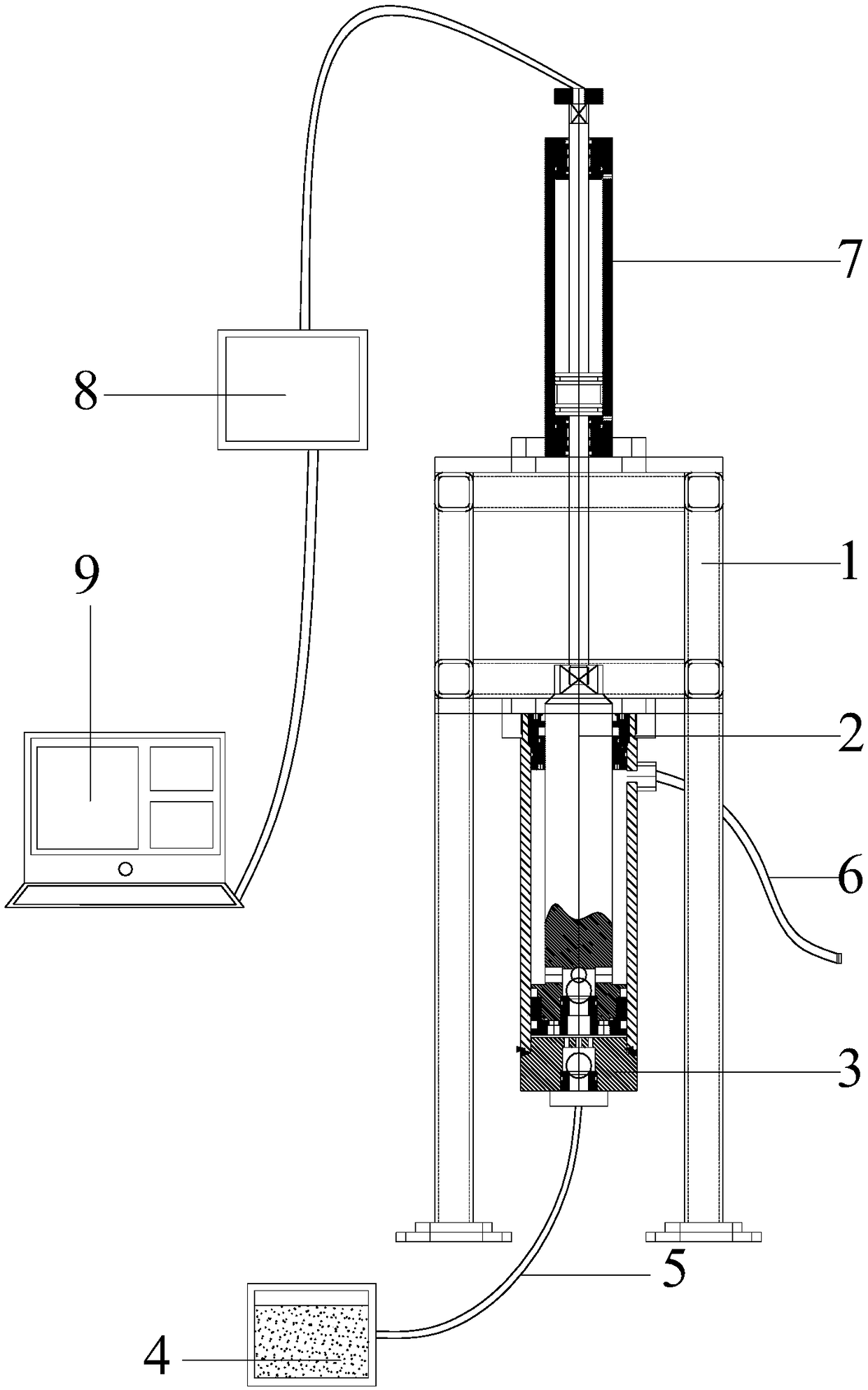
[0114] This embodiment provides an intelligent non-pulse grouting pump for indoor model tests, and its specific realization structure is as follows figure 1 As shown, it may specifically include the following components:
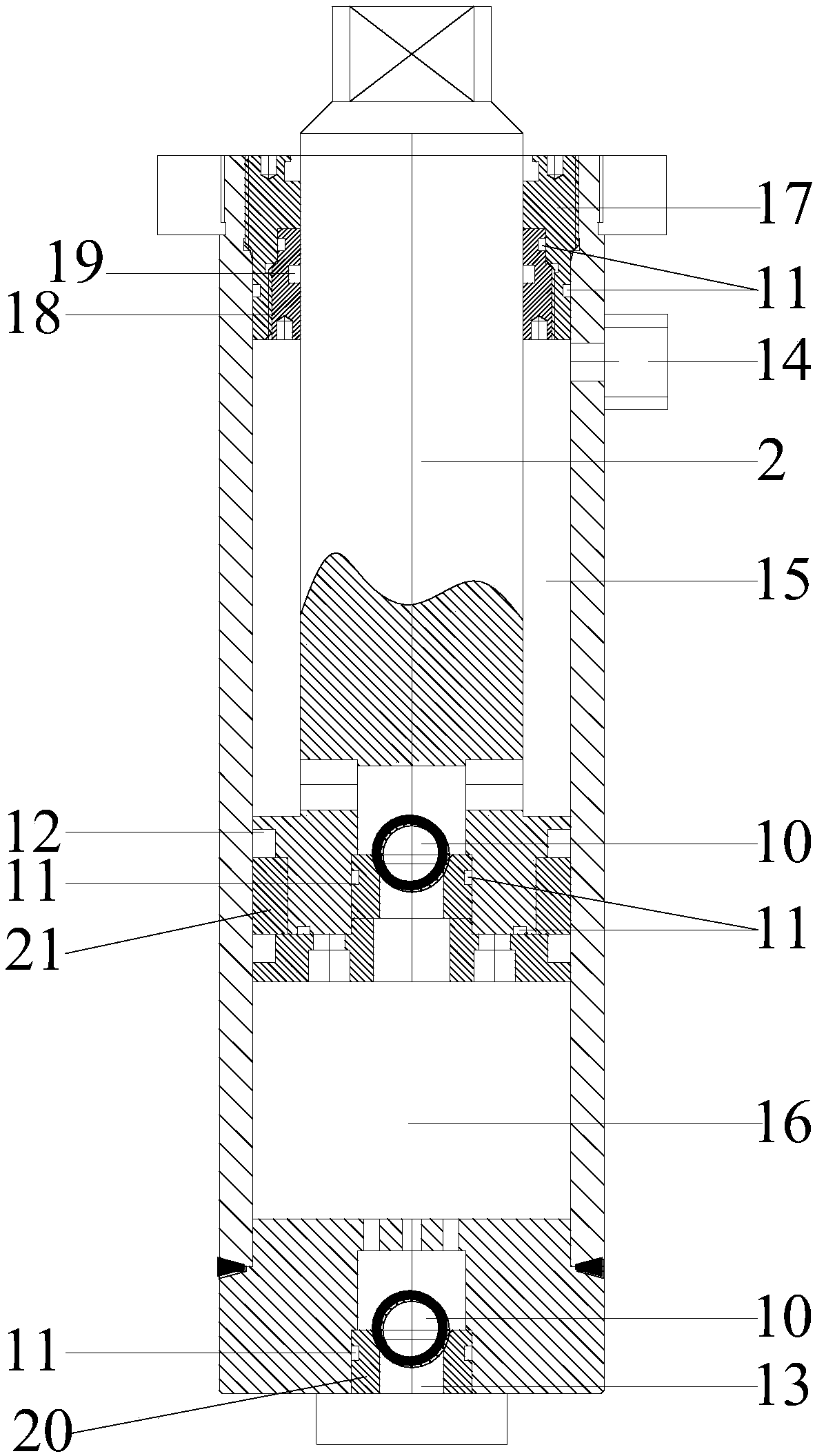
[0115] An intelligent non-pulse grouting pump for indoor model testing, including: pump body 1, piston rod 2, pumping system 3, slurry storage tank 4, slurry delivery pipe 5, slurry delivery pipe 6, propulsion cylinder 7, hydraulic system 8 and PLC control system 9; the pumping system 3 is installed on the pump body 1, the pumping system 3 is connected with the propulsion cylinder 7 through the piston rod 2, and the propulsion cylinder 7 is controlled by the hydraulic system 8 Provide power to realize propulsion control, the PLC control system 9 transmits the signal to the servo valve on the hydraulic system 8 to control the reciprocating motion of the propulsion cylinder 7, the pumping system 3 is connected to the slurry delivery pipe 5 and The slurry outl...
PUM
 Abstract
Description
Claims
Application Information
 - R&D
- Intellectual Property
- Life Sciences
- Materials
- Tech Scout
- Unparalleled Data Quality
- Higher Quality Content
- 60% Fewer Hallucinations
Browse by: Latest US Patents, China's latest patents, Technical Efficacy Thesaurus, Application Domain, Technology Topic, Popular Technical Reports.
© 2025 PatSnap. All rights reserved.Legal|Privacy policy|Modern Slavery Act Transparency Statement|Sitemap|About US| Contact US: help@patsnap.com


