
array substrate

A technology for array substrates and substrates, applied in instruments, semiconductor devices, optics, etc., can solve problems such as peeling, abnormal contact of conductive layers, and low occurrence rate of PFA layer peeling, so as to improve yield, improve adhesion, and reduce peeling The effect of the risk

Active Publication Date: 2020-09-29
SHENZHEN CHINA STAR OPTOELECTRONICS SEMICON DISPLAY TECH CO LTD
View PDF10 Cites 0 Cited by
  • Summary
  • Abstract
  • Description
  • Claims
  • Application Information

AI Technical Summary

Problems solved by technology

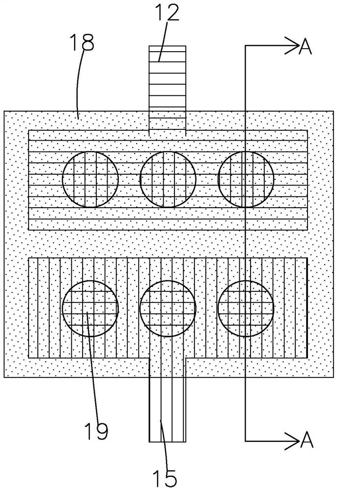
However, in the PFA process, it is easy to cause poor peeling of the PFA layer, especially in the area of ​​the out-of-plane transfer hole, where the incidence of PFA layer peeling is very high, while the incidence of PFA layer peeling in the in-plane via area is very high. Low
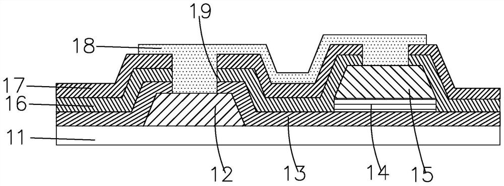
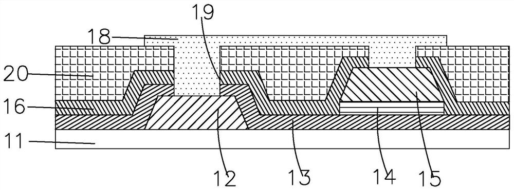
On the array substrate of existing PFA products, the PFA layer is prone to peeling off in the peripheral circuit area. The reason is that the PFA layer in the peripheral circuit area is directly arranged on the first passivation layer, and the PFA layer in the display area It is set on the color resist layer, the adhesion between the PFA layer and the color resist layer is better than that of the first passivation layer, and the second is that the via holes of the PFA layer in the display area are set in the via holes of the color resist layer Inside, there is color resistance behind the via holes of the PFA layer, so the PFA layer is not easy to peel off when the air knife blows through the array substrate, but there is no color resistance behind the via holes of the PFA layer in the peripheral display area, and the air knife When blowing, it is easy to blow up the PFA layer in the peripheral display area, causing the PFA layer to peel off at the peripheral via holes, and the peeling of the PFA layer will cause abnormal contact of the conductive layer, and finally cause abnormal lighting screen

Method used


Image

  • array substrate
  • array substrate
  • array substrate

Examples


Embodiment Construction

[0030] In order to further illustrate the technical means adopted by the present invention and its effects, the following describes in detail in conjunction with preferred embodiments of the present invention and accompanying drawings.

[0031] see Figure 4-6, the present invention provides an array substrate, including a display area 6 and a peripheral circuit area 3 located on the periphery of the display area 6 .

[0032] The peripheral circuit area 3 includes a peripheral region substrate 31, a peripheral region TFT layer 32 disposed on the peripheral region substrate 31, a peripheral region passivation layer 33 disposed on the peripheral region TFT layer 32, and a peripheral region passivation layer 33 disposed on the peripheral region passivation layer 33. The color resistance layer 34 on the color resistance layer 34, the peripheral area PFA layer 35 disposed on the color resistance layer 34, and the connecting line layer 36 disposed on the peripheral area PFA layer 35...


PUM


Abstract

The present invention provides an array substrate, the peripheral circuit area of ​​which includes a peripheral region substrate, a peripheral region TFT layer, a peripheral region passivation layer, a color resist layer, a peripheral region PFA layer, and a connecting line layer arranged in sequence from bottom to top. The resistance layer is provided with a first via hole, and the PFA layer in the peripheral area is correspondingly provided with a second via hole in the first via hole, and the hole wall of the second via hole belongs to the PFA layer in the peripheral area, and the peripheral area The passivation layer is correspondingly provided with a third via hole connected to the second via hole under the second via hole, and the corresponding second via hole and the third via hole together form a transfer via hole, and the connecting line The layer is in contact with the TFT layer in the peripheral area through the transfer via hole, and the color resistance layer is set between the passivation layer in the peripheral area and the PFA layer in the peripheral area, and the via hole for transfer in the PFA layer in the peripheral area is set in the color In the barrier layer, the adhesion of the PFA layer in the peripheral area can be improved, and the risk of peeling off of the PFA layer in the peripheral area can be reduced, thereby improving the yield of PFA products.

Description

technical field [0001] The present invention relates to the field of display technology, in particular to an array substrate capable of reducing the risk of peeling off of the peripheral PFA layer. Background technique [0002] Active thin film transistor liquid crystal display (Thin Film Transistor-LCD, TFT-LCD) has been developed rapidly and widely used in recent years. Most of the liquid crystal display devices currently on the market are backlight liquid crystal display devices, which include a liquid crystal display panel and a backlight module. Generally, a liquid crystal display panel consists of a color filter (Color Filter, CF) substrate, a thin film transistor substrate (Thin Film Transistor, TFT), a liquid crystal (Liquid Crystal, LC) sandwiched between the color filter substrate and the thin film transistor substrate, and a sealant ( Sealant) composition. [0003] COA (Color-filter on Array) technology is an integrated technology that directly manufactures colo...

Claims


Application Information

Patent Timeline
Patent Type & Authority Patents(China)
IPC IPC(8): G02F1/1362G02F1/1368H01L27/12
CPCH01L27/1214G02F1/136209G02F1/136286G02F1/1368G02F1/1345H01L27/1248G02F1/136222
Inventor 周平赵国鹏
Owner SHENZHEN CHINA STAR OPTOELECTRONICS SEMICON DISPLAY TECH CO LTD
Learn More