Low-consumption network device based on temperature differential power generation
A technology of network equipment and temperature difference power generation, which is applied in the construction of electrical equipment components, electrical components, and adjustment of electrical variables, etc., can solve the problems of large power consumption and poor heat dissipation effect, and achieve improved service life, improved heat dissipation performance, and improved stability sexual effect
- Summary
- Abstract
- Description
- Claims
- Application Information
AI Technical Summary
Problems solved by technology
Method used
Image
Examples
Embodiment 1
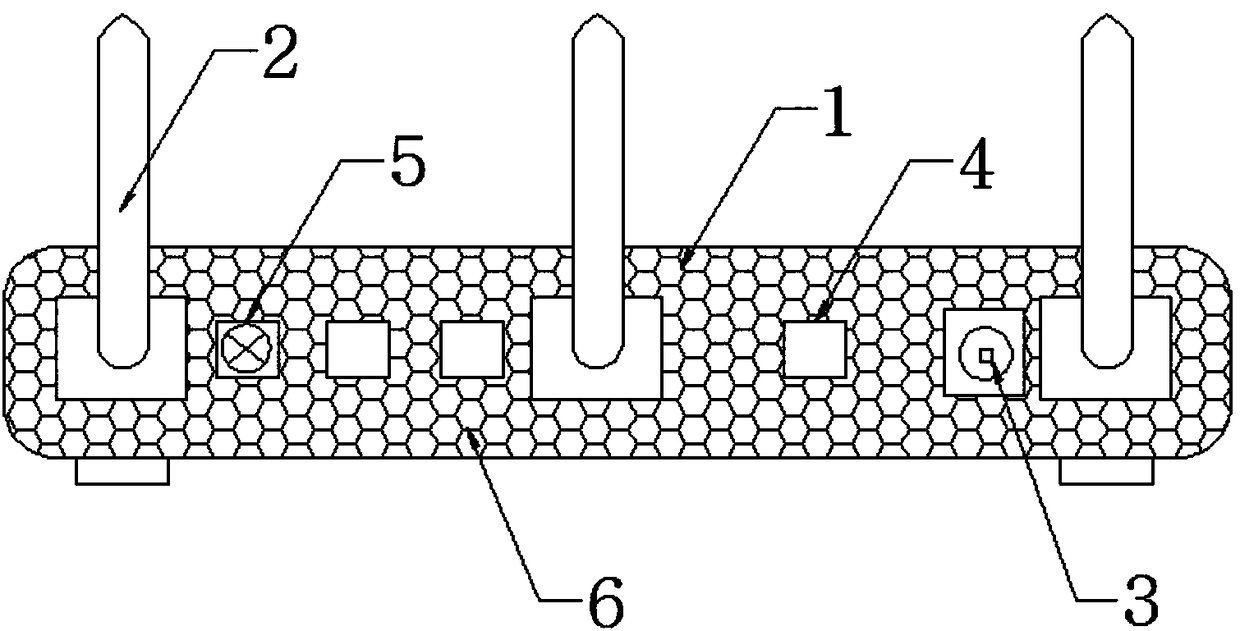
[0021] A low-consumption network device based on temperature difference power generation, comprising a network device body 1, an antenna 2 arranged on the network device body 1, a network interface 4 and a power supply interface 3 arranged on the side wall of the network device body 1, inside the network device body 1 A thermoelectric power generation circuit is provided, a fan 5 is installed on the side wall of the network equipment body 1, and the thermoelectric power generation circuit supplies power to the fan 5, and a ventilation hole 6 is provided on the side wall of the network equipment body 1. Power is supplied to the fan 5 through the thermoelectric power generation circuit to reduce power load, realize low power consumption and reduce generated heat at the same time.
Embodiment 2
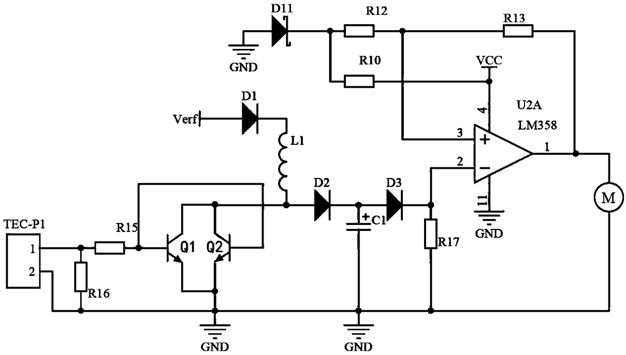
[0023] The thermoelectric power generation circuit includes a thermoelectric power generation unit, a boost unit and a voltage stabilizing unit electrically connected in sequence, and the boost unit includes resistors R15, R16, R17, triode Q1, triode Q2, diode D1, diode D2, and diode D3 , inductance L1 and capacitor C1; both ends of the first interface and the second interface of the thermoelectric power generation unit are connected to the two ends of the resistor R16, and the second interface is grounded, the resistor R16 is connected to the resistor R15 and then connected to the base of the transistor Q1, and the emitter of the transistor Q1 and the transistor Q1 is grounded. The collectors of transistor Q1 and transistor Q2 are connected to inductor L1, the base of transistor Q2 is connected to the base of transistor Q1, the inductor L1 is connected to the cathode of diode D1, the anode of diode D1 is connected to the adjustable voltage input terminal, and the inductor L1 is...
PUM
 Abstract
Description
Claims
Application Information
 - R&D
- Intellectual Property
- Life Sciences
- Materials
- Tech Scout
- Unparalleled Data Quality
- Higher Quality Content
- 60% Fewer Hallucinations
Browse by: Latest US Patents, China's latest patents, Technical Efficacy Thesaurus, Application Domain, Technology Topic, Popular Technical Reports.
© 2025 PatSnap. All rights reserved.Legal|Privacy policy|Modern Slavery Act Transparency Statement|Sitemap|About US| Contact US: help@patsnap.com


