Main rotor shaft of single rotor unmanned aerial vehicle and processing technology thereof

A technology of main rotor shaft and processing technology, which is applied in the direction of metal material coating technology, shaft, mechanical equipment, etc., can solve problems such as safety hazards, impact resistance, wear resistance, and service life limitations, so as to improve performance , Guarantee the effect of excellent quality and high precision

Pending Publication Date: 2018-08-14
珠海市凯菱机械科技有限公司
View PDF5 Cites 1 Cited by
  • Summary
  • Abstract
  • Description
  • Claims
  • Application Information

AI Technical Summary

Problems solved by technology

[0002] The main rotor shaft of the existing UAV is often processed in one piece by a lathe, and then the corresponding precision requirements are met through finishing machining, and then heat treatment, chrome plating and other processes are performed to improve the performance of the main rotor shaft. The performance of the rotor shaft meets the corresponding requirements, but for the main rotor shaft with high standard requirements, when the inside of the main rotor shaft with a larger diameter is processed, it cannot meet its performance and meet the high standard requirements, and it has not been completely processed. , so there are limitations in impact resistance, wear resistance and service life, which will cause safety hazards during use

Method used


Image

  • Main rotor shaft of single rotor unmanned aerial vehicle and processing technology thereof
  • Main rotor shaft of single rotor unmanned aerial vehicle and processing technology thereof
  • Main rotor shaft of single rotor unmanned aerial vehicle and processing technology thereof

Examples


Embodiment Construction

[0031] The present invention will be further described in detail below in conjunction with the embodiments and the accompanying drawings, but the embodiments of the present invention are not limited thereto.

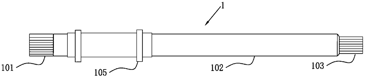
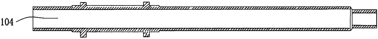
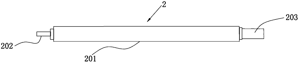
[0032] Such as Figure 1 to Figure 3 As shown, the main rotor shaft of a single-rotor UAV includes a main shaft 1 and an auxiliary shaft 2, the main shaft 1 and the auxiliary shaft 2 are cylindrical, and the main shaft 1 includes a shaft head 101 and a shaft body 102 and the shaft tail 103, the diameter of the shaft tail 103 is smaller than the diameter of the shaft body 102, the shaft head 101 and the shaft tail 103 are both spline shafts, and the main shaft 1 is provided with an inner hole 104 arranged along the direction of the central axis , the auxiliary shaft 2 includes a body 201 and a connecting portion 202 and a fixing portion 203 arranged at both ends of the body, the body 201 of the auxiliary shaft 2 is connected with the inner hole 104 through a transition fi...


PUM

PropertyMeasurementUnit
surface smoothnessaaaaaaaaaa
diameteraaaaaaaaaa
depthaaaaaaaaaa

Abstract

The invention relates to a main rotor shaft of a single rotor unmanned aerial vehicle. The main rotor shaft comprises a main shaft and an auxiliary shaft, wherein the main shaft and the auxiliary shaft are cylindrical; the main shaft comprises a shaft head, a shaft body and a shaft tail; the diameter of the shaft tail is smaller than that of the shaft body; the shaft head and the shaft tail are spline shafts; an inner hole formed along the direction of a central shaft is formed in the main shaft; the auxiliary shaft comprises a body and a connecting part and a fixing part arranged at two endsof the body; the body of the auxiliary shaft is connected to the inner hole in transition fit; the concentricity of the main shaft and the auxiliary shaft is 0.01mm; the fixing part is connected to the inner hole in the shaft tail in transition fit; nitriding layers are arranged on the surfaces of the shaft head and the shaft tail; and chromium coatings are arranged on the surface of the shaft body, the surface of the inner hole and the surface of the auxiliary shaft. The invention provides the main rotor shaft of the single rotor unmanned aerial vehicle simple in structure, high in precisionand impact resistant. Moreover, the main rotor shaft is excellent in processing technology and high in precision and meets the high standard demand.

Description

technical field [0001] The invention relates to the technical field of UAV processing, in particular to a main rotor shaft of a single-rotor UAV and a processing technology thereof. Background technique [0002] The main rotor shaft of the existing UAV is usually processed by a lathe in one piece, and then the corresponding precision requirements are met through finishing machining, and then heat treatment and chrome plating are performed to improve the performance of the main rotor shaft. The performance of the rotor shaft meets the corresponding requirements, but for the main rotor shaft with high standard requirements, when processing the inside of the main rotor shaft with a large diameter, it cannot meet the high standard requirements, and the processing is not complete. , so there are limitations in impact resistance, wear resistance and service life, which will cause safety hazards during use. Contents of the invention [0003] The purpose of the present invention ...

Claims


Application Information

Patent Timeline
Patent Type & Authority Applications(China)
IPC IPC(8): F16C3/02C21D9/28C21D1/25C23C30/00C23C8/00B23P15/00
CPCF16C3/023C21D1/25C21D9/28C23C8/00C23C30/00B23P15/00B23P2700/01
Inventor 周玉君
Owner 珠海市凯菱机械科技有限公司
Why Eureka
Try Eureka