Automatic slag removal biomass combustion device as well as combustion engine and combustion method

A combustion device and automatic slag removal technology, applied in the direction of combustion method, combustion air/fuel supply, combustion equipment, etc., can solve the problems of unfavorable popularization and application, burnout of boilers, investment of labor and time, etc., so as to reduce the use and promotion Low cost, extended service life, and wide applicability

Pending Publication Date: 2018-08-14
河南奥兰斯特新能源技术有限公司
View PDF14 Cites 5 Cited by
  • Summary
  • Abstract
  • Description
  • Claims
  • Application Information

AI Technical Summary

Problems solved by technology

[0003] At present, the common biomass burners on the market are mainly designed for horizontal flame injection. This design makes it easy to burn the boiler wall and burn out the boiler when the flame is sprayed into the boiler. In order to solve this problem, some people use the boiler furnace The in-depth transformation has been carried out, which has caused the problem of high cost of comprehensive use of biomass fuels; at the same time, due to the problem of coke slag produced by the biomass fuel itself, it is necessary to manually remove slag from the burner, which needs to be shut down to remove slag, and requires Investing labor and time, resulting in the problem that the overall efficiency of this type of burner is not high, which is not conducive to popularization and application

Method used


Image

  • Automatic slag removal biomass combustion device as well as combustion engine and combustion method
  • Automatic slag removal biomass combustion device as well as combustion engine and combustion method
  • Automatic slag removal biomass combustion device as well as combustion engine and combustion method

Examples


Embodiment 1

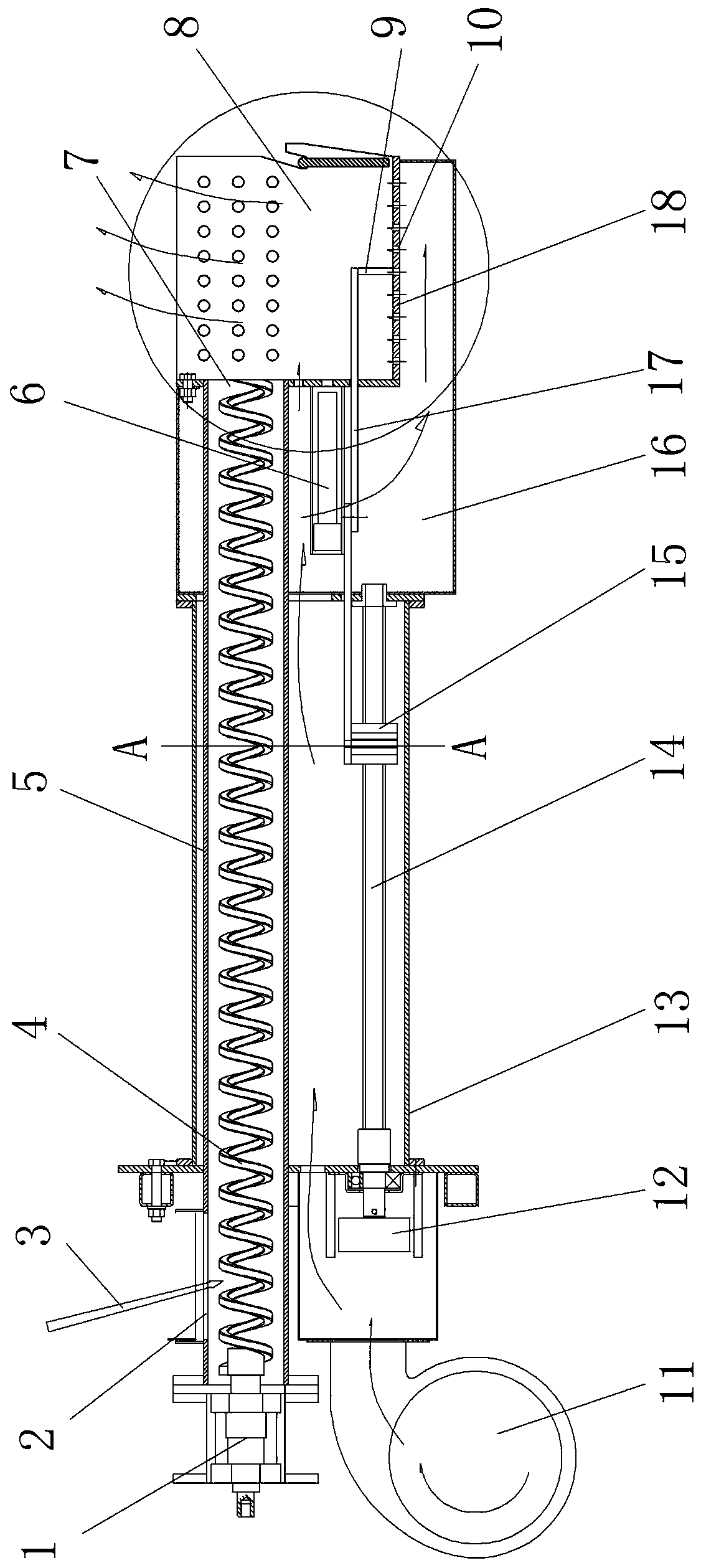
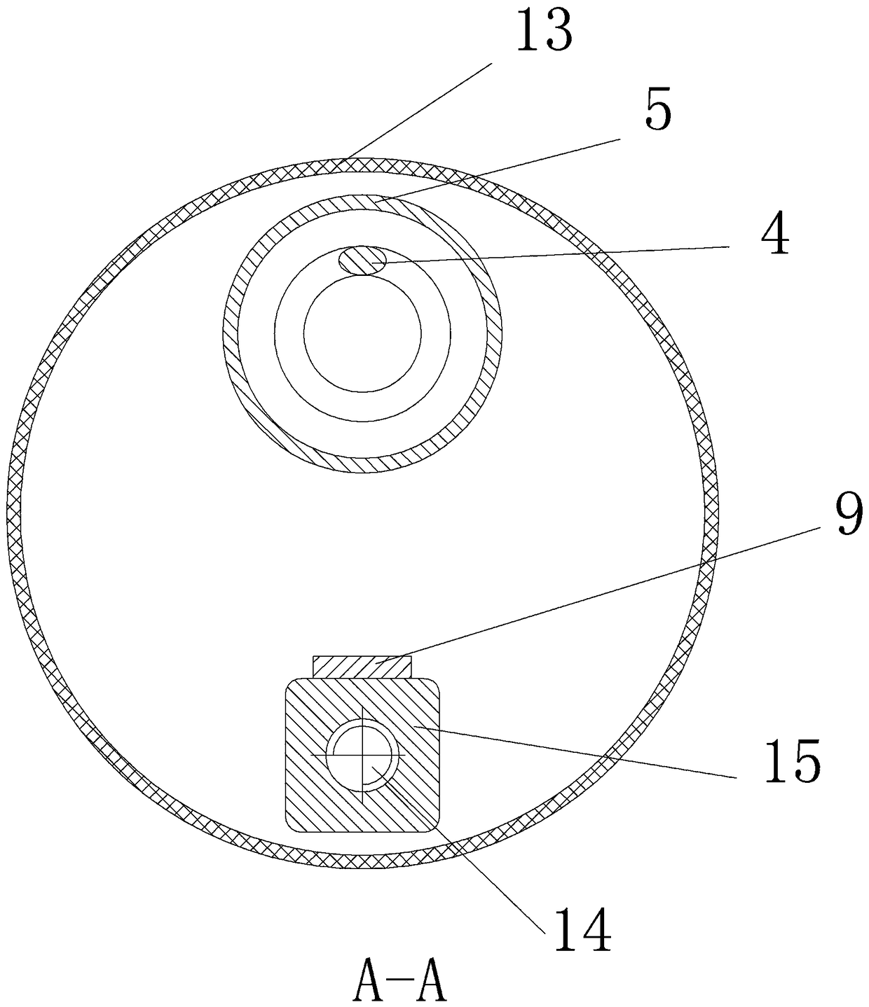
[0035] Embodiment one: see Figure 1-3 , an automatic slag removal biomass combustion device in the figure, the device includes a blower device, a feeding device, a combustion chamber, and a slag removal device,

[0036] The blowing device includes a fan and an air duct; the air duct is a horizontal closed channel, one end is connected to the fan, and the other end is connected to the combustion chamber.

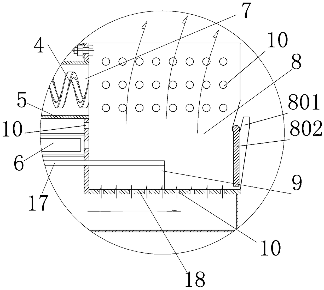
[0037] The combustion chamber includes a material combustion chamber and an air distribution chamber with an L-shaped cross section. The air distribution chamber is located between the material combustion chamber and the air duct. The outer and upper sides of the material combustion chamber are open, and a number of There are several air distribution holes evenly distributed on the rear panel of the combustion chamber and the upper part of the side panels of the combustion chamber, and the air distribution holes are connected to the air distribution chamber and the material ...

Embodiment 2

[0041] Embodiment two, see Figure 1-4 In the figure, a biomass burner comprising the automatic deslagging biomass combustion device described in Embodiment 1, the burner also includes a funnel-shaped silo and a silo frame, and the feeding pipe of the combustion device passes through the fastener and the silo The frame is fixedly connected, the feed bin is located at the upper half of the bin frame, and the lower outlet of the feed bin is connected to the feed port of the feed pipe of the combustion device. In this way, the biomass fuel in the silo can directly enter the feed pipe, and the side of the silo is equipped with a transparent observation hole, which is used to penetrate the amount of biomass fuel in the silo, so that it can be replenished in time; There are universal wheels, which are used as walking wheels when transporting the burner; the feeding pipe of the combustion device is fixed on the warehouse frame through the fixing plate, which is used to install the co...

Embodiment 3

[0043] Embodiment three, see Figure 1-4 In the figure, a method for using the automatic decoking biomass burner described in Embodiment 2 includes the following steps:

[0044] ①. Feeding

[0045] Put the granular biofuel into the silo, and judge whether the fuel is flame-resistant. If it is flame-resistant, hang the baffle at the front of the combustion chamber;

[0046] ②.Feeding and air supply

[0047] Turn on the feeding motor and fan, on the one hand, the biomass fuel is sent to the material combustion bin, and at the same time, the fan disperses the combustion-supporting air into the material combustion bin through the air duct, the air distribution chamber, and the air distribution holes on the lower part and side of the material combustion bin;

[0048] ③. Ignition

[0049] The material falling into the combustion chamber is ignited by the ignition device and starts to burn, and the ignition device goes out when the temperature rises to the set value; the burner bu...


PUM


Abstract

The invention discloses an automatic slag removal biomass combustion device as well as a combustion machine and a combustion method. The automatic slag removal biomass combustion device as well as thecombustion machine and the combustion method have the beneficial effects that the comprehensive optimization design is carried out on the arrangement of a material combustion bin and an air duct, anoriginal combustion mode of transverse fire discharge is changed, and a scraping plate capable of doing reciprocating motion is arranged in the combustion bin, and therefore, the coke slag and the ashin the combustion bin can be cleared in time, then the downward ventilation is not influenced, and the heat conversion rate of biomass fuel can be improved; and the combustion device enables the flame to be directly combusted, the defect that a boiler wall is burnt by the transverse flame is avoided, and therefore the upward combustion enables the heat to be more concentrated, the applicability is wide, the requirements of most existing boiler hearths can be met, the adaptive design is not needed to be carried out on the boiler, the use and popularization cost of the combustion machine is reduced, meanwhile, the service life of the boiler is prolonged, and multiple purposes are achieved.

Description

technical field [0001] The invention relates to biomass treatment equipment, in particular to an automatic slag removal biomass combustion device, a burner and a combustion method. Background technique [0002] With the aggravation of environmental pollution and the adverse effects of the polluted environment on people's production and life, people are paying more and more attention to the protection of the environment. The biomass burner processes biomass into particles for efficient combustion, which plays an important role in reducing the damage to the environment caused by extensive outdoor burning. [0003] At present, the common biomass burners on the market are mainly designed for horizontal flame injection. This design makes it easy to burn the boiler wall and burn out the boiler when the flame is sprayed into the boiler. In order to solve this problem, some people use the boiler furnace The in-depth transformation has been carried out, which has caused the problem ...

Claims


Application Information

Patent Timeline
Patent Type & Authority Applications(China)
IPC IPC(8): F23B40/00F23K3/00F23L1/00F23L5/02F23J1/06
CPCF23B40/00F23J1/06F23K3/00F23L1/00F23L5/02
Inventor 许兰贵王自勇王洁王现平张雅叙
Owner 河南奥兰斯特新能源技术有限公司
Why Eureka
Try Eureka