
LED quantum dot light emitting device and packaging method thereof

A quantum dot light-emitting, quantum dot technology, applied in semiconductor devices, electrical components, circuits, etc., can solve the problem of reducing the light conversion stability of quantum dot light conversion coatings, reducing the conversion efficiency of quantum dot light conversion coatings, and reducing device light. Effectiveness, CRI and service life, etc., to achieve high thermal reliability, avoid aging failure, and improve service life.

Pending Publication Date: 2018-08-14
SOUTH CHINA UNIV OF TECH
View PDF5 Cites 2 Cited by
  • Summary
  • Abstract
  • Description
  • Claims
  • Application Information

AI Technical Summary

Problems solved by technology

Therefore, a large amount of heat will be thermally conducted from the LED light-emitting chip to the quantum dot light conversion coating, which will reduce the conversion efficiency of the quantum dot light conversion coating, reduce the stability of the light conversion of the quantum dot light conversion coating, and make the quantum dot light conversion coating Rapid aging and failure of the coating will eventually reduce the performance of the device such as light efficiency, CRI and service life

Method used


Image

  • LED quantum dot light emitting device and packaging method thereof
  • LED quantum dot light emitting device and packaging method thereof
  • LED quantum dot light emitting device and packaging method thereof

Examples


Embodiment Construction

[0045] The present invention will be further described in detail in conjunction with the accompanying drawings and specific embodiments.

[0046] In order to facilitate a unified review of the various reference signs in the drawings of the specification, the unified description of the reference signs appearing in the drawings of the specification is as follows:

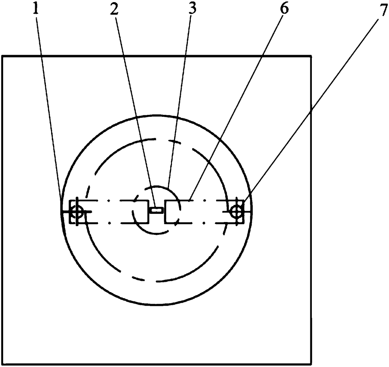
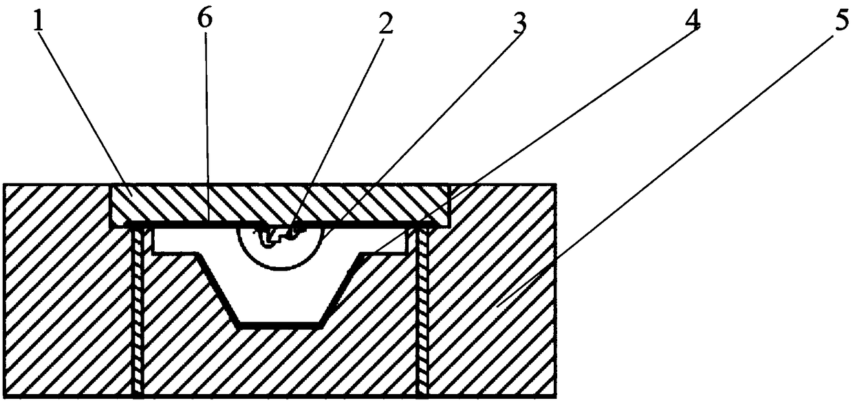
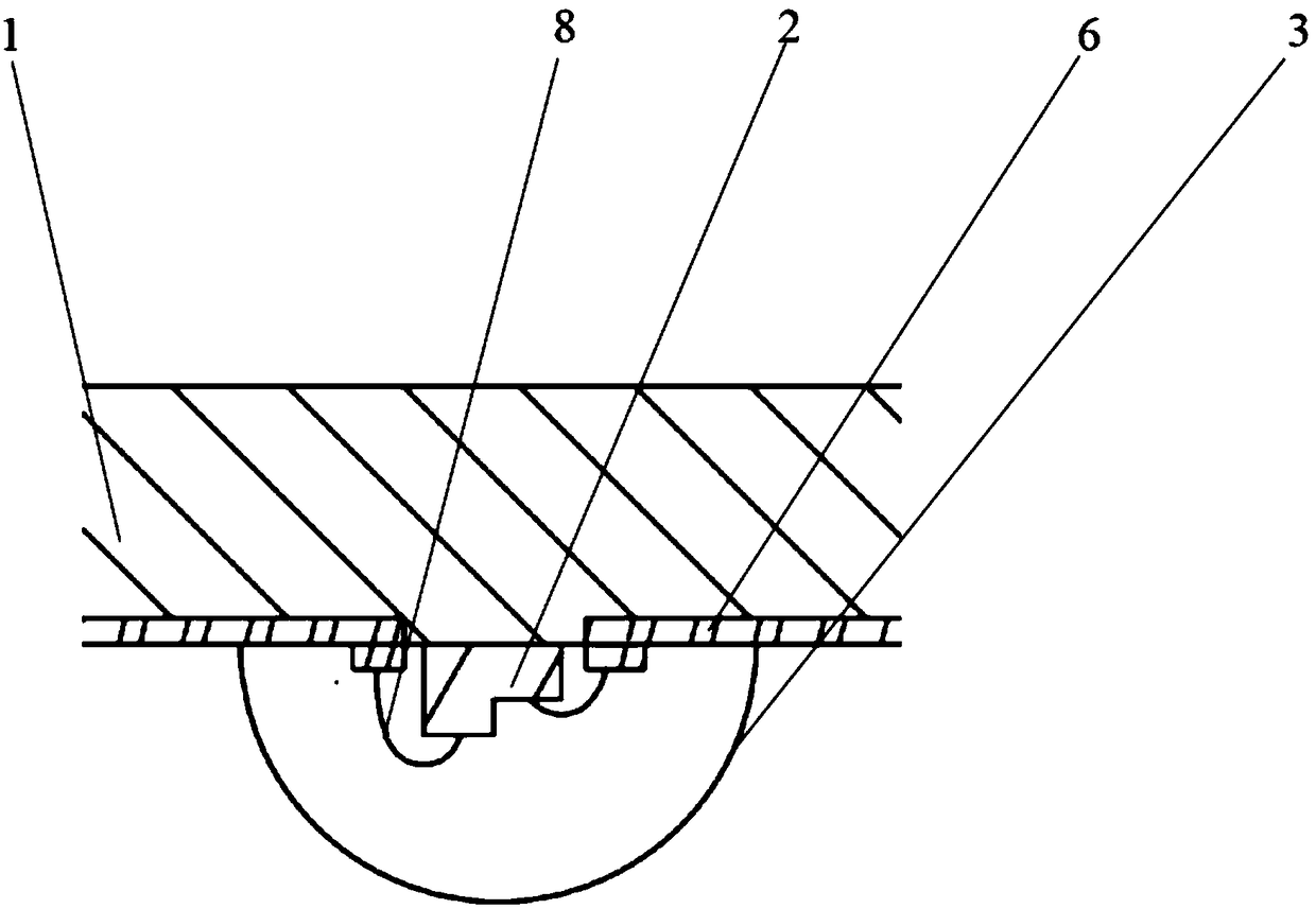
[0047] 1 is the glass top cover, 2 is the LED light-emitting chip with the formal structure, 3 is the light-taking lens, 4 is the quantum dot light conversion coating, 5 is the insulator high thermal conductivity support, 6 is the electrode metal layer, 7 is the electroplated copper column, 8 is the Lead wire, 9 is a flip-chip LED light-emitting chip, 10 is a metal conductor high thermal conductivity support, 11 is an insulating layer, 12 is a first plane, 13 is an inclined plane, 14 is a second plane, 15 is a first vertical plane, and 16 is a second plane. Three planes, 17 is the second vertical plane.

[0048] For ...


PUM


Abstract

The invention relates to an LED quantum dot light emitting device, comprising a glass top cover, an LED light emitting chip, a light extracting lens, a quantum dot optical conversion coating layer anda heat conducting bracket; a positive electrode metal layer and a negative electrode metal layer are arranged on the lower end plane of the glass top cover; the LED light emitting chip is fixed on the lower end plane of the glass top cover; the positive electrode of the LED light emitting chip is electrically connected with the positive electrode metal layer while the negative electrode of the LED light emitting chip is electrically connected with the negative electrode metal layer; the light extracting lens is fixed on the lower end plane of the glass top cover and coats the LED light emitting chip; an inner cavity is formed in the heat conducting bracket; the quantum dot optical conversion coating layer is arranged on the surface of the inner cavity of the heat conducting bracket; the heat conducting bracket has a positive conductive electrode and a negative conductive electrode; the positive conductive electrode of the heat conducting bracket is electrically connected with the positive electrode metal layer; and the negative conductive electrode of the heat conducting bracket is electrically connected with the negative electrode metal layer. The invention also relates to a packaging method of the LED quantum dot light emitting device. By virtue of the device, high-quality light can be generated stably, belonging to the technical field of a light emitting device.

Description

technical field [0001] The invention relates to the technical field of light emitting devices, in particular to an LED quantum dot light emitting device. Background technique [0002] In traditional LED quantum dot light-emitting devices, the LED light-emitting chip is solidified on the bottom surface of the bracket, and the quantum dot light-conversion coating is coated on the top of the LED light-emitting chip, resulting in direct contact between the quantum dot light-conversion coating and the LED light-emitting chip. Due to factors such as current injection efficiency, radiative luminescence quantum efficiency, and external light extraction efficiency of the chip when the LED light-emitting chip is powered on, only about 30% of the input electric energy is converted into light energy, and the remaining about 70% of the energy is generated by non-radiative recombination. Transform heat energy in the form of lattice vibrations. Therefore, a large amount of heat will be th...

Claims


Application Information

Patent Timeline
Patent Type & Authority Applications(China)
IPC IPC(8): H01L33/48H01L33/50H01L33/64
CPCH01L33/486H01L33/507H01L33/641H01L2933/0033H01L2933/0041
Inventor 徐书恒李宗涛汤勇李家声颜才满曹凯
Owner SOUTH CHINA UNIV OF TECH
Learn More